
Company Honda Company Ford Company Skoda Company Kia Company Mazda Company Mercedes Company Renault
English Русский
Български
Беларускі
Український
Српски
Hrvatski
Română
Polski
Slovenský
Magyar
Bookmark Articles Sitemap Contacts
ToyotaMan.ru


Camry Corolla Corona Carina Land Cruiser Highlander 4Runner RAV4 Others
Cruiser 100 (1998-2007) Cruiser 60/80 (1980-1997, petrol) Cruiser 70 (1985-1996, diesel)

Battery Charging System — Design Description [Toyota Land Cruiser J60]

  • Main
  • Land Cruiser
  • J60 (1980-1997)
  • Power unit
  • Engine electrical equipment
  • Battery Charging System — Design Description
0

Battery charging circuit diagram (1988-92.)
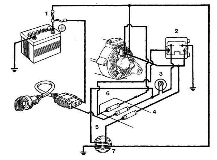


1. Fusible link; 2. Control lamp relay; 3. Control lamp; 4. ENGINE fuse; 5. GAUGE fuse; 6. Charging circuit fuse; 7. Ignition control relay


Battery charging circuit diagram (since 1993)
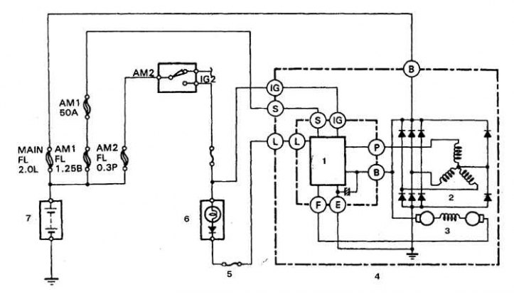


1. Voltage regulator; 2. Stator; 3. Rotor; 4. Generator; 5. Fuse 7.5 A; 6. Control lamp; 7. Battery


The charging system consists of an alternator, a voltage regulator, a charge control lamp circuit, a battery, a fuse link and connecting wires. When these devices work together, they supply power to such consumers as the ignition system, lighting and signaling devices, a radio receiver, etc. The generator is driven by a belt.

Attention! Generators of 1980-87 are equipped with a built-in voltage regulator, which is mounted on the side of the generator body, access to it is possible without removing the generator.


Attention! The voltage regulator on generators of 1988-92 is mounted on the rectifier inside the generator housing.


Attention! On cars since 1993, the regulator is made integral with the brush holder unit, access to the regulator is provided after removing the generator and the rear cover.


1980-87 vehicles are equipped with an ignition relay that supplies power to the charging and ignition circuit fuses.

1988-92 vehicles are equipped with a relay that illuminates the low battery warning light. 1993 and later vehicles have additional fuses and links that monitor the integrity of various parts of the charging circuit.

The voltage regulator is designed to maintain the generator voltage at a given level. When the voltage at the generator output increases sharply, the regulator prevents current surges and overloads in the power supply circuit.

Periodic maintenance of the charging system is generally not required. However, the alternator drive belt, battery and connecting cables should be inspected periodically.

The charge indicator lamp on the instrument panel lights up when the ignition is turned on and goes out after the engine starts. If the lamp does not go out after the engine starts, then the charging circuit is faulty. Some cars are equipped with a voltmeter. If the voltmeter shows very high or very low voltage, then the charging circuit needs to be checked.

Precautionary measures


When connecting the vehicle's internal circuit wires and external devices, the following precautions should be observed.


When connecting the battery to the generator, always observe the correct polarity.

Before repairing any part of the vehicle with electric welding, disconnect the wires from the generator and from the battery terminal.

It is not allowed to start the engine with the charger connected.

Always disconnect the vehicle's circuit cables from both battery terminals before connecting the charger.

The generator is connected directly to the battery, so if the generator terminals are shorted or overloaded, an arc may form and cause a fire.

Before flushing the engine with a jet of steam, cover the generator with plastic film and secure the film with a rubber bandage.
This article is available at: russian, bulgarian, belarusian, ukrainian, serbian, croatian, romanian, polish, slovak, hungarian
The article material has been checked: Evdokimov Evgeniy
Share information:
◀ Previous
Cruiser 60/80: Engine electrical equipment
Next ▶

Inductive sensor — checking and replacement
Electronic Ignition Unit — Replacement
Ignition distributor — removal and installation
Ignition Coil — Checking and Replacing
Checking the ignition system
Checking the battery charging system
Generator — removal and installation
Generator Parts — Disassembly, Inspection and Assembly
Engine starting system — design description
Starter solenoid relay (cars produced in 1980-87)
Similar articles on other Toyota models

➥ Battery Charging System — Design Description Toyota 4Runner N120 (1989-1995)
➥ Battery Charging System — Description and Testing Toyota Camry XV20 (1996-2001)
➥ Charging system — design description Toyota Corolla Verso 3 (2004-2009)
➥ Description of the design of the engine lubrication system Toyota Corona T190 (1992-1997)
➥ Precautions when working with the charging system Toyota Carina T190 (1992-1996)
➥ Variable Valve Timing (VVT) System — Design Description and… Toyota Highlander 1 (2000-2007, petrol)
Link in different formats to this article
Comments and feedback from visitors
No comments yet


Add two numbers 39 + 21


Cruiser 100 (1998-2007) 
  • General information
  • Introduction to the guide
  • Controls and instruments
  • Maintenance
  • Power unit
  • Petrol engines
  • Diesel engines
  • Cooling and heating
  • Power and exhaust systems
  • Engine electrical equipment
  • Engine management systems
  • Transmission
  • Automatic gearbox
  • Transmission line
  • Chassis, running gear
  • Brake system
  • Car suspension
  • Steering
  • Body and interior
  • Exterior (external elements)
  • Interior (internal elements)
  • Doors, locks and windows
  • Electrical equipment
  • Equipment and devices
  • Electrical circuits
Cruiser 60/80 (1980-1997, petrol) 
  • General information
  • User manual
  • Maintenance
  • Power unit
  • Petrol engines 2F and 3F-E
  • Petrol engines 1FZ-FE
  • Engine overhaul
  • Engine electrical equipment
  • Cooling and heating
  • Fuel system (carburetor)
  • Fuel system (injector)
  • Toxicity reduction system
  • Transmission
  • Car gearbox
  • Clutch
  • Transfer case
  • Drive shafts and axles
  • Chassis, running gear
  • Brake system
  • Car suspension
  • Steering
  • Body and interior
  • Exterior and interior
  • Doors, locks and windows
  • Electrical equipment
  • Equipment and devices
  • Electrical circuits
Cruiser 70 (1985-1996, diesel) 
  • General information
  • User manual
  • Maintenance
  • Power unit
  • Engine adjustment
  • Engine repair
  • Fuel system
  • Control system
  • Turbocharging system
  • Cooling and lubrication system
  • Charge and start system
  • Transmission
  • Clutch
  • Mechanical gearbox
  • Automatic gearbox
  • Transfer case
  • Chassis, running gear
  • Car suspension
  • Brake system
  • Steering
  • Body and interior
  • Body elements
  • Heating and air conditioning
  • Electrical equipment
  • Equipment and devices
  • Electrical circuits
ToyotaMan.ru © 2018–2026 • Mobile version • Interesting about Toyota • Administration • Sitemap: EN BG BY UA RS HR RO PL SK HU • Search system • Bookmark
Camry Vista-V40 • Camry XV10 • Camry XV20 • Camry XV30 • Corolla Verso-AR10 • Corolla E80 • Corona T190 • Carina T170 • Carina T190 • Land Cruiser J70 (diesel) • Land Cruiser J60 (petrol) • Land Cruiser J100 • Highlander XU20 (petrol) • 4Runner N120 • RAV4 XA10 • RAV4 XA20 • Duet M100 • Dyna Y50 •
We require cookies to enable some interactive features. Is that ok with you?