



Contents: Removal ↓ Installation ↓
Engine cylinder head 2F
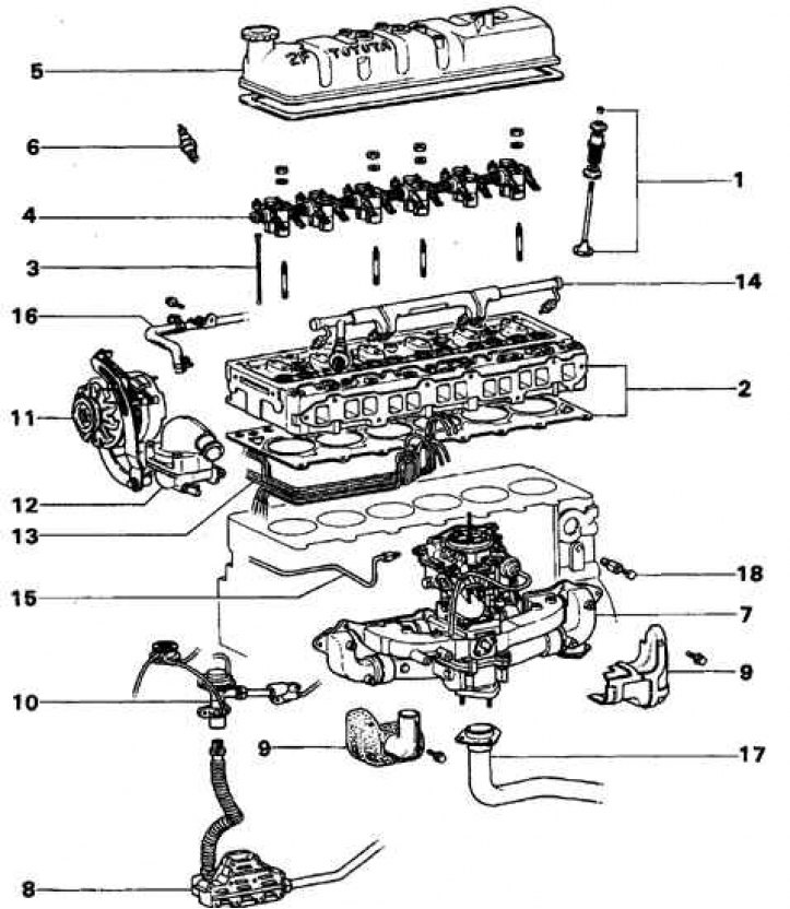
1. Spring and valve; 2. Gasket; 3. Push rod; 4. Rocker arms with rollers; 5. Lid; 6. Candle; 7. Intake and exhaust manifolds; 8. Recirculation system cooler; 9. Shield; 10. Recirculation valve; 11. Generator; 12. Thermostat; 13. Vacuum tubes; 14. Air duct; 15. Gasoline pipeline; 16. Oil cooler hose; 17. Exhaust pipe; 18. Drain plug
Cylinder head of the 3F-E engine
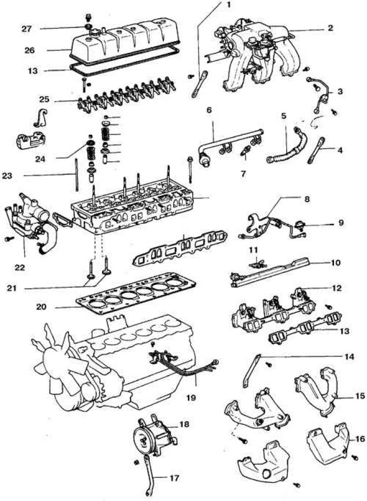
1, 4. Air intake chamber stand; 2. Air intake chamber; 3. Starter nozzle tube; 5. Recirculation tube; 6. Air duct; 7. Fitting; 8. Fuel line N1 with hook for hanging the engine; 9. Pulse suppressor (pressure regulator); 10. Fuel distributor; 11. Nozzle; 12. Suction manifold; 13, 20. Gasket; 14. Manifold stand; 15. Exhaust manifold; 16. Heat shield; 17. Air pump stand; 18. Air pump; 19. Gasoline N₂; 21. Valves; 22. Coolant outlet manifold; 23. Barbell; 24. Rotator; 25. Rocker arms with rollers; 26. Lid; 27. Seal
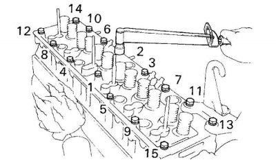
Cylinder Head Bolt Tightening Sequence
Attention! Work is performed on a cold engine.
Removal
1. Remove the rocker arms and rods.
2. Remove the manifolds.
3. Remove the drive belts.
4. Remove the power steering pump and set it aside without disconnecting the lines.
5. Remove the air pump with bracket (see subsection 6.3).
6. Remove the air duct (see Fig. Cylinder head of engine 2F and Fig. Cylinder head of engine 3F-E).
7. Drain the coolant, unscrew the temperature sensor.
8. Remove the air conditioning compressor (if provided) and move it to the side without disconnecting the lines.
9. Loosen the bolts in the reverse order indicated (see Fig. Cylinder Head Bolt Tightening Sequence). Carefully remove the cylinder head. If the head is difficult to remove, carefully tap it with a hammer through a wooden block.
Installation
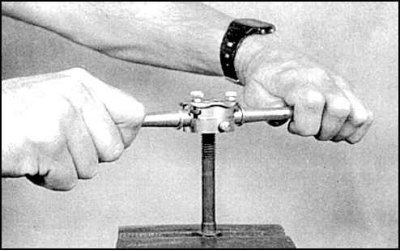
1. Clean the separating surfaces of the cylinder head and block. Run the threads of the studs and holes.
2. Check the split surfaces of the head and cylinder block for burrs, chips, dents and other damage. Check the deformation of the head surface. Minor damage can be removed with a file; in case of serious damage, the head or block must be re-ground.
3. The gasket is made of composite material and is installed without sealant.
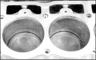
4. Install the gasket with the TOP label facing up.
5. Carefully install the head on the cylinder block, without disturbing the position of the gasket. Tighten the cylinder head bolts by hand and tighten the bolts to the specified torque in the specified sequence (see Fig. Cylinder Head Bolt Tightening Sequence).
6. Then the assembly is carried out in the reverse order. Fill the cooling system with liquid, add oil and replace the filter. Start the engine, make sure there are no leaks. Test the vehicle's driving characteristics.