



Removal and installation
Note! These parts can be removed without dismantling the cylinder head. To do this, the valve must be held with compressed air or a device.
1. Remove the cylinder head cover.
2. Remove the spark plug from the cylinder on which the valve train components will be changed, or all the spark plugs.
3. Set the piston of the 1st cylinder to TDC of the compression stroke. If all the oil seals are to be replaced, start the replacement with the 1st cylinder and then change them sequentially, setting each cylinder to TDC in accordance with the engine operating order.
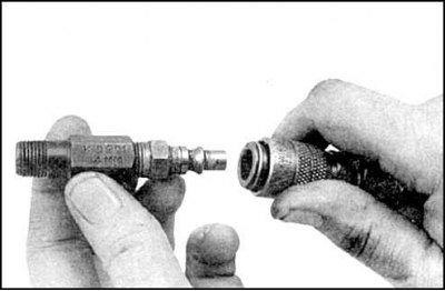
4. Screw the adapter into the spark plug hole.
5. Remove the shaft and rocker arm(s), take out the push rod.
6. Supply compressed air to the cylinder at TDC while holding the crankshaft with a wrench.
7. The valves should be pressed against the seats.
8. If there is no compressed air, insert a piece of thick nylon rope into the hole before the piston reaches TDC. Then turn the crankshaft until you feel resistance when pulling out the rope.
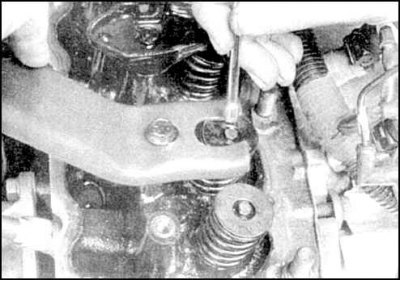
9. Plug all holes in the cylinder head with a rag and compress the spring with a device. Remove the crackers.
10. Remove the tool, oil deflector cup, spring and cap.
Caution: If an air leak is detected at this stage (if applicable), then the cylinder head should be removed for disassembly and repair.
11. Relieve air pressure by wrapping the valve with tape or turning the crankshaft slightly in the direction of normal rotation.
12. Check the condition of the valve stem and its deformation by turning the valve in the sleeve.
13. Check the freedom of translational movement of the valve in the sleeve. If the valve is stuck, then either the valve is bent or the sleeve is damaged. In this case, the cylinder head should be removed for disassembly and repair.
14. Re-lock the valve (by supplying air or by pushing a piece of rope through).
15. Lubricate the rod and put on a new cap.
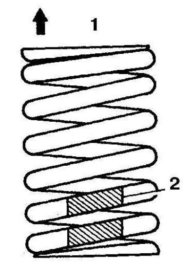
16. Install the spring (it should be facing down with the color marking (2)) and the cup (1 – up).
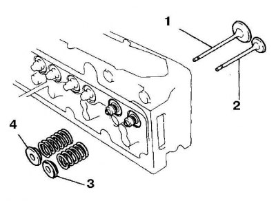
17. A rotator (3) is installed on the exhaust valves (2), there is one groove on the stems of these valves. A plate (4) is installed on the intake valves (1), there are 2 grooves on the stems of these valves (3F-E engine).
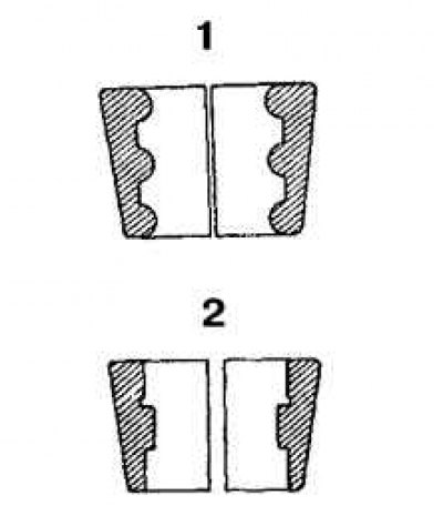 | 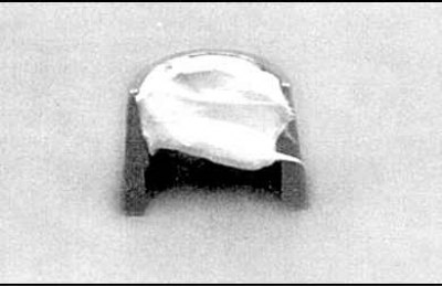 |
18. Install the crackers (figure on the left, 1 - inlet valve cracker, 2 - outlet valve cracker), securing them with grease (photo on the right).
19. Remove the device and install all removed parts in reverse order.
20. Start the engine, check for leaks and listen to the valve mechanism operation.