A) Clean the bolts and bolt holes of sealant residue.
b) Apply sealant to the threads of the front cover mounting bolts.
Sealant: Part No. 088330-00070 Three Bond 1324 or equivalent
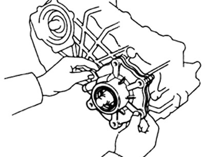
V) Install the front cover with a new gasket on the transfer box adapter and tighten the mounting bolts.
Tightening torque - 64 N.m
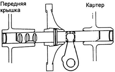
2. Install the rear output shaft front bearing holder into the front cover.
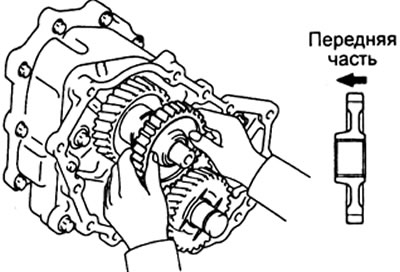
3. Installation of the intermediate gear assembly.
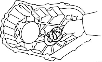
A) Apply gear oil to a new o-ring and install it into the recess on the front of the idler shaft.
b) Install the intermediate gear shaft into the front cover.
V) Install the thrust washer on the shaft. Note: Make sure that the lug of the thrust washer aligns with the groove on the front crankcase cover.
G) Install idler gear assembly with needle bearings and spacer.
d) Apply gear oil to a new o-ring and install it into the recess in the intermediate gear shaft.
4. Apply grease to a new O-ring and install it on the transmission output shaft.
5. Using the special tool, install the transfer case drive gear onto the transmission output shaft.
6. Installation of the drive gear of the power take-off mechanism.
A) Install the spacer on the gearbox output shaft.
b) Install the PTO drive gear onto the transmission output shaft.
V) Install the bearing using the special tool.
7. Install the rear output shaft assembly with the high-low shift fork assembly.
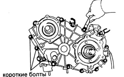
8. Installing the transfer case housing.
A) Use grease to secure the thrust washer to the crankcase.
Note: Make sure the thrust washer lug aligns with the groove on the crankcase.
b) Install a new gasket on the front crankcase cover.
V) Install the crankcase by aligning the splines of the inner lever and the high-low shift fork shaft.
G) Tighten the fourteen mounting bolts.
Tightening torques:
- turnkey bolt 17 - 64 N.m
- turnkey bolt 14 - 39 N.m
9. Plug installation.
A) Clean the plug and the hole under it from the remnants of the sealant.
b) Apply sealant to the threads of the plug.
Sealant:
- Part No. 088330-00070,
- Three Bond 1324 or equivalent
V) Install the ball and spring, then tighten the plug.
Tightening torque - 44 N.m
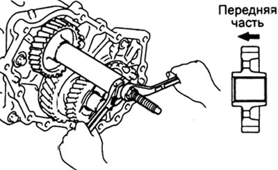
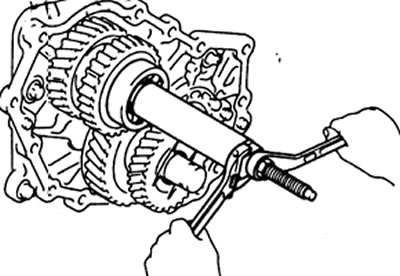
10. Install the idler shaft retainer plate and tighten the mounting bolt.
Tightening torque - 21 N.m
11. Install the spacer, speedometer drive gear and washer onto the rear output shaft.
12. Adjustment of the pull-off torque of the rear output shaft bearings.
A) Install the output shaft rear bearing retainer onto the crankcase, aligning the ribs. Tighten the mounting bolts.
Tightening torque - 34 N.m
b) Temporarily install a new rear output shaft connecting flange locknut.
V) Set the external high-low shift lever on the crankcase to position "N".
G) Measure the breakaway torque of the rear output shaft bearings.
Bearing breakaway moment:
- new - 1.5-2.4 N.m
- in operation - 0.7-1.2 N.m
d) If the breakaway torque is not within acceptable limits, then remove the outer race of the output shaft rear bearing '. Select a new shim according to the table.
| Label | Thickness | Label | Thickness |
| 0 | 0.15 mm | 10 | 1.0 mm |
| 4 | 0.40 mm | 11 | 1.1mm |
| 5 | 0.50 mm | 12 | 1.2 mm |
| 6 | 0.60 mm | 13 | 1.3mm |
| 7 | 0.70 mm | 14 | 1.4mm |
| 8 | 0.80 mm | 15 | 1.5mm |
| 9 | 0.90 mm |
Note:
- If the breakaway moment is too high, then reduce the thickness of the washer; if the moment is too small, then increase the thickness of the washer.
- When installing the next thickest shim, the breakaway torque will change by 1.0 Nm.
e) Remove the connecting flange lock nut and the rear bearing retainer.
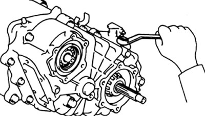
14. Installation of the holder of the rear bearing of the output shaft.
A) Clean the bolts and bolt holes of sealant residue.
b) Apply sealant to the threads of the holder mounting bolts.
Sealant: Part No. 088330-00070 Three Bond 1324 or equivalent
V) Install a new gasket on the transfer case housing.
G) Install the rear bearing holder onto the crankcase, aligning the ribs. Tighten the mounting bolts.
Tightening torque - 34 N.m
15. Installing the connecting flange of the rear output shaft.
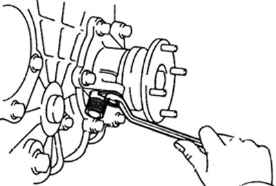
A) Install the connecting flange, washer and locknut. While holding the flange with the special tool, tighten the locknut.
Tightening torque - 127 N.m
b) Using a hammer and chisel, tap the locknut.
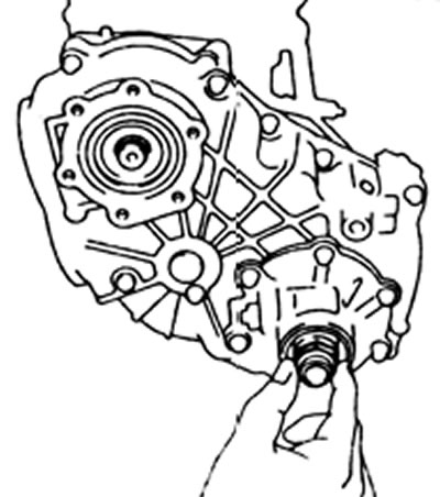
16. Installing the locknut for securing the gearbox output shaft.
A) Set the external high-low shift lever on the crankcase to position "H2" or "14"
b) Install the washer.
V) While holding the rear output shaft connecting flange with the special tool, tighten the locknut.
Tightening torque —— 127 N.m
G) Using a hammer and chisel, tap the locknut.
17. Installing the rear crankcase cover,
A) Clean the bolts and bolt holes of sealant residue.
b) Apply sealant to the threads of the rear cover mounting bolts.
Sealant: Part No. 088330-00070 Three Bond 1324 or equivalent
V) Install the rear cover along with a new gasket on the crankcase and tighten the six mounting bolts.
Tightening torque - 15 N.m
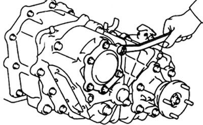
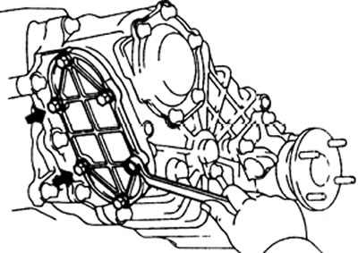
18. Installing the side cover (for power take-off).
A) Clean the two bolts and bolt holes of sealant residue.
b) Apply sealant to the threads of the two side cover mounting bolts.
Sealant:
- Part No. 088330-00070,
- Three Bond 1324 or equivalent
V) Install a new gasket and side cover to the crankcase. Install the two bolts covered with sealant and the remaining four bolts as shown.
Tightening torques:
- bolts with sealant - 17 N.m
- other bolts - 19 N.m
19. Installation of the driven gear of the speedometer drive.
A) Apply transmission oil to the new O-ring
b) Install the o-ring on the driven gear.
V) Install the driven gear into the output shaft rear bearing holder, then install the lock plate and tighten the mounting bolt.
Tightening torque - 13 N.m
20. Install the low gear switch (L4).
Tightening torque - 25 N.m
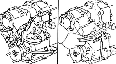
21. Connect the two sensor connectors on the transfer case.