
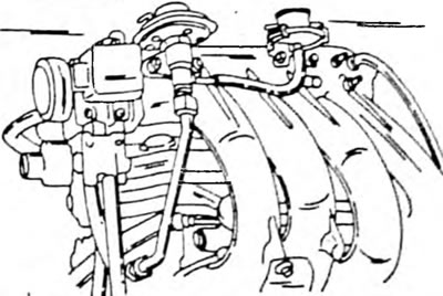
The cylinder head is made of light metal alloys and operates with transverse scavenging, that is, the intake and exhaust valves are located opposite each other. The spark plugs are screwed into the combustion chambers. The intake manifold has 8 long intake pipes; The intake manifold of a carburetor engine is heated by coolant.
On the 1.6 liter engine, the exhaust camshaft is belt driven. The exhaust camshaft gear meshes with the intake camshaft gear. The camshafts are mounted in five bearings. Bearings are lubricated through a channel in the center of the shaft. On the 2.0L engine, both camshafts are driven in the same way, only the second camshaft drive gears are located in the middle of both camshafts. On the 1.6L engine, both camshaft gears are located at the front of the cylinder head.
Adjustment of valve clearances on both engines is carried out by replacing the shims between the valves and valve lifters; the replacement is made without removing the camshafts.
The timing belt cover consists of three parts (1.6 l engine) or two parts (2.0 l engine). Inspection hole in the bottom cover (on 1.6 l engines) or in the top cover (on 2.0 l engines) provides the ability to adjust the tension of the toothed belt.
The pistons are made of heat-resistant metal and have recesses to prevent valve impacts. Piston pins on all engines are installed in the same way, that is, the pins are pressed into the connecting rod heads and pistons "swim" on fingers. Each piston has two compression rings and one oil scraper ring.
Before starting work, you need to thoroughly clean all external surfaces of the engine. To prevent foreign objects from entering, first cover all openings in the engine with clean rags.
Engine disassembly will be described in detail below in the subsection "Repair and refurbishment". Thus, we will be able to describe the work that is carried out both on the removed and without removing the engine, without describing the disassembly work twice. If it is necessary to carry out a complete disassembly, it is necessary to combine individual work processes, and in a given order. In general, during disassembly, all moving and moving parts should be marked to ensure they are installed in the same places. This is especially important for pistons, valves, bearing caps and bearing shells. Place the removed parts so as not to mix them up.
Do not mark supporting or sealing surfaces under any circumstances with a scribe or stamp. Paint is best for marking. When removing the bearing shells of the crank mechanism, the places where they are installed should also be marked, that is, either on the side of the mechanism housing or on the side of the bearing cover. The numbers of the main and connecting rod bearings are marked on the rear side of the corresponding bearing shell.
It is best to place the valves on the bottom of an inverted cardboard box, and write the valve numbers next to it. In Fig. Figure 4 shows the location of the removed valves in numerical order. It is also impossible to confuse the valves of one cylinder. It is best to place the inlet valves on one side and the outlet valves on the other side, that is, you can lay the valves on the bottom in this manner by folding two cardboard boxes. Most parts are made of aluminum and should be handled accordingly. If hammering is required to seat the part, use only rubber, plastic or leather hammers. If you don't have a mounting stand, it's best to cut suitable wooden blocks onto which to mount the engine so that you can access it from the top and bottom. Once removed, the cylinder head can be clamped in a vice using a metal bracket screwed to the intake manifold studs.
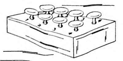
Fig.4. The valves can be placed on the bottom of an inverted cardboard box, with inlet valves on one side and exhaust valves on the other.
The normal engine disassembly sequence is described below, and some removal details are detailed below in the appropriate subsections. The cylinder head can be removed without removing the engine. Tension adjustment and toothed belt replacement can also be done without removing the engine.
Disassemble the engine in the following sequence:
Engine 4A-F and Engine 4A-FE (1.6 l)
- Unscrew the water pump pulley nuts, loosen the V-belt adjusting bolt and remove the V-belt (Pic. 5). Remove the pulley from the water pump.
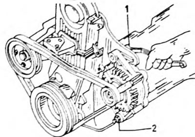
Fig.5. To remove the V-belt, loosen the two bolts and nuts (1) And (2).
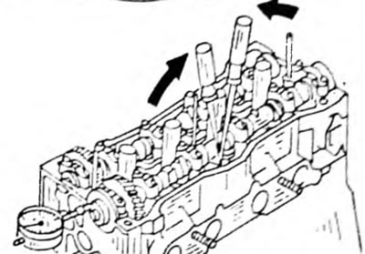
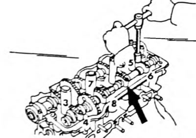
- Remove four spark plugs. To do this, you need to insert a long spark plug wrench into the individual holes, which is shown in Fig. 6. Before doing this, remove the ignition wires.
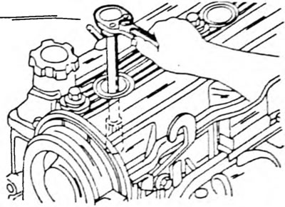
Pic. 6. A long spark plug wrench is required to remove the spark plugs.
- Disconnect the crankcase ventilation hose from the ventilation valve.
- Unscrew the three cylinder head cover nuts and remove the cover with the nut sealing washers and gasket. During installation, the sealing washers are replaced.
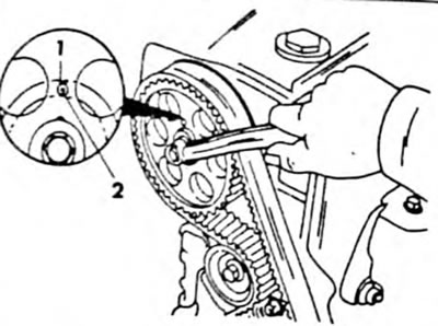
- Rotate the crankshaft pulley until the mark aligns with the mark "0" on the timing belt cover. Check if there is any play in the valve tappets of the first cylinder. If there is no play, turn the engine one more revolution. In Fig. Figure 7 shows the installation of the crankshaft pulley so that the engine is at TDC.
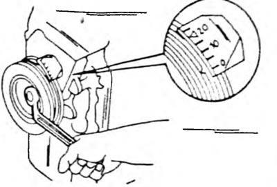
Pic. 7. Turn the crankshaft with a spanner wrench until it reaches the mark "0" with a mark on the pulley.
- Unscrew the crankshaft pulley and remove it from the shaft using a puller. The pulley has two threaded holes for screwing in a puller, as shown in Fig. 8.
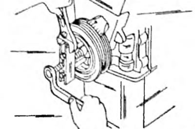
Fig.8. Removing the crankshaft pulley using a special puller
- Unscrew the upper, middle and lower timing belt covers and remove the gaskets. Remove 9 bolts in total.
- Remove the timing belt drive pulley. It is put on the front side of the crankshaft and is simply removed as shown in Fig. 9.
Pic. 9. Removing the timing belt pulley from the front side of the crankshaft. Pay attention to how the washer is put on.
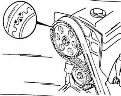
- If the toothed belt is to be installed again, mark it with an arrow for the direction of movement and marks for its location relative to the camshaft gear and crankshaft pulley, as can be seen in Fig. 10.
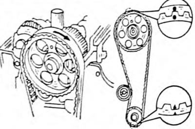
Pic. 10. Draw an arrow for the direction of movement, as shown on the left side of the figure. The right figure shows the relative positions of the timing belt gears.
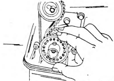
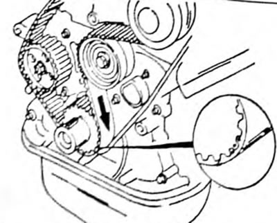
- Loosen the toothed belt tensioner bolt at the front of the engine, press the tensioner to the left using a screwdriver, as shown in Fig. 11, and tighten in this position. The timing belt is now free of tension and can be removed. If necessary, you can remove the belt tension roller.
Pic. 11. Use a screwdriver to press out the tensioner and tighten the bolt again.
- Remove the timing belt sprocket from the crankshaft. If necessary, use a strong screwdriver or pry bar.
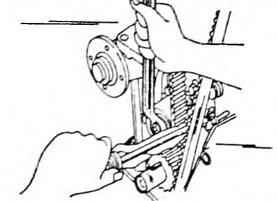
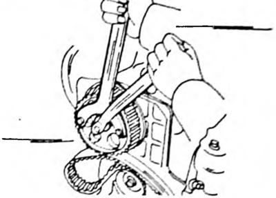
- Loosen the camshaft gear bolt. The shaft must be kept from turning. In the place shown in Fig. 12, there is a hexagon on the shaft where you can install a wrench. Do not damage the cylinder head when pressing the wrench into it.
Pic. 12. Hold the camshaft when unscrewing the camshaft gear bolt.
- Loosen the ignition distributor screws, disconnect the vacuum hose and remove the ignition distributor along with the wires connected to it.
- Unscrew the drain pipe (2 bolts).
- Unscrew the two bolts and remove the exhaust manifold support.
- Remove the four bolts and upper exhaust manifold heat shield.
- Unscrew the three bolts and two nuts of the exhaust manifold and remove the exhaust manifold with gaskets, unscrew three more bolts and remove the lower exhaust manifold heat shield.
- Remove the cooling system inlet housing. To do this, disconnect two water hoses, unscrew two nuts and one bolt (Pic. 13) and remove the housing.
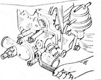
Pic. 13. Removing the cooling system inlet housing
- On carburetor engines, remove the fuel pump.
- Disconnect the crankcase ventilation hose, disconnect the water hose from the intake manifold and remove the two intake manifold support bolts.
- Unscrew the six bolts and two nuts, remove the cable clamp and remove the intake manifold with gasket.
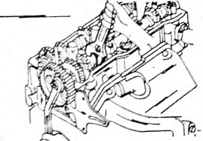
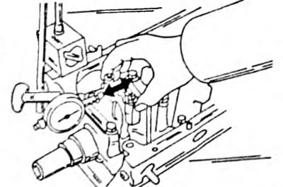
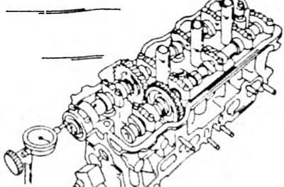
- Measure the axial play of both camshafts. To do this, install a dial indicator at the end of the camshaft, as shown in Fig. 14, and use two screwdrivers to move the camshaft in both directions. Take readings from the dial indicator. The intake camshaft play should be in the range from 0.030 to 0.085 mm; The exhaust camshaft play should be in the range from 0.035 to 0.090 mm.
Pic. 14. Measuring the axial play of the F/FE engine camshaft. Check both shafts in the specified way
- Since the axial play of the camshafts is very small, the camshaft must be kept straight when removed. Otherwise, the cylinder head may be damaged or even broken. Therefore, the following instructions must be followed precisely:
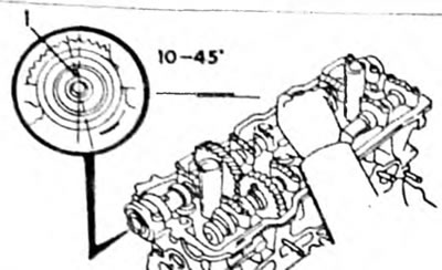
— Turn the intake camshaft until the hole on the gear is in the position shown in Fig. 15.
Pic. 15. Rotate the intake camshaft until the hole (1) on the gear wheel is in the indicated position
— Unscrew the bolts of the bearing caps No. 1 of the intake and exhaust camshafts one by one and remove both caps.
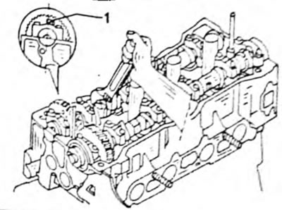
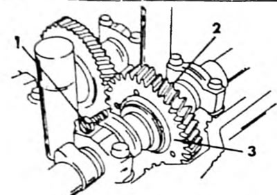
— Fasten both separate gears of the intake camshaft to each other by screwing an M6 bolt 16-20 mm long into the wheels, as shown in Fig. 16. This releases the tension on the torsion spring of the secondary gear.
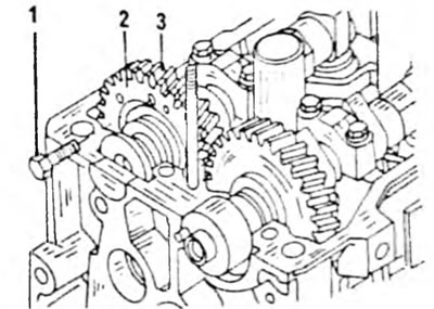
Pic. 16. Before removing the intake camshaft, pass a bolt through both parts of the intake camshaft gear. 1. M6 bolt; 2. Secondary gear; 3. Main gear
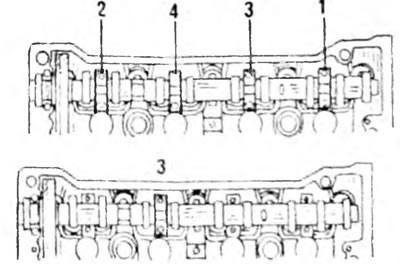
— Evenly loosen the bolts of the four remaining bearing caps in the order shown in Fig. 17. Sequentially remove the bearing caps and pull out the intake camshaft. Under no circumstances should you use a screwdriver or similar tool to remove the shaft. If it is impossible to pull out the camshaft in a horizontal position, reinstall bearing cap No. 3 (below in Fig. 17), tighten evenly and then loosen the bolts evenly again, pulling the camshaft wheel up. The camshaft is disassembled. These works are described in chapter 2.8.

Pic. 17. Sequence of loosening the camshaft bearing cap bolts. The location of the bearing cap No. 3 is shown below
- To remove the exhaust camshaft, rotate it until its pin is in the position shown in Fig. 18.
Pic. 18. Rotate the exhaust camshaft to the alignment pin (1) to the specified position. Only then can the camshaft be removed.
- Unscrew the camshaft bearing caps in the same way as described for the intake camshaft and pull out the shaft.
- Using a Torx wrench, loosen the cylinder head bolts in the sequence shown in Fig. 19. Loosening the bolts in a different sequence may cause the cylinder heads to become misaligned. Raise the cylinder head. If the head is stuck, insert a screwdriver as shown in Fig. 20, between the protrusion on the motor block and the head, without damaging the surface. The head sits on pins.
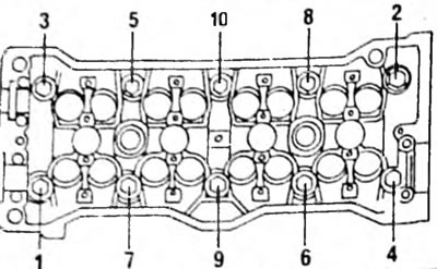
Pic. 19. Sequence of loosening the cylinder head bolts
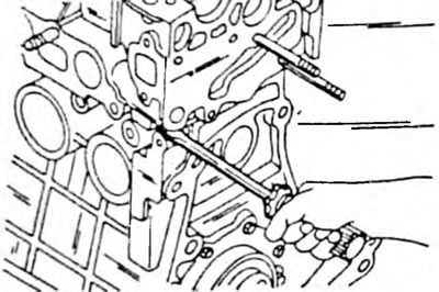
Pic. 20. Separate the cylinder head using the indicated method.
- Turn the engine over and remove the oil pan. The pallet is secured with two nuts and 19 bolts. Due to the sealant, the oil pan may sit very tightly and may need to be pressed out. When installing the tool to press out the oil pan, do not damage the oil pan flange. After removing the oil pan, remove the gasket.
- Unscrew the filter mesh at the bottom of the crank mechanism housing.
- Unscrew the crank mechanism housing from the front part and pull out the oil pump. The pump is secured with seven bolts. To remove the pump, they should be knocked out of the crank mechanism housing with a plastic hammer. Remove the pump gasket.
- Before disassembling the crank mechanism, check the axial play of the four crankshaft connecting rod bearings. To do this, place a dial indicator on the cylinder block, as shown in Fig. 21, press the connecting rod to one side and reset the dial indicator scale to zero. After this, press the connecting rod in the other direction and take readings from the dial indicator scale. Normal play is 0.15 to 0.25 mm, but a wear limit of 0.30 mm is acceptable. If the play is greater than the specified value, the bearing or crankshaft must be replaced. Also measure the axial play of other connecting rod bearings.
Pic. 21. Measure the axial play of the connecting rod bearings on all axles of the crankshaft. To do this, move the bearing in both directions in the direction of the arrows.
- Number the connecting rod bearing caps and connecting rods. To do this, use a core, as shown in Fig. 22. Make one punch with a center punch on the first connecting rod, two blows on the second connecting rod, etc. When removing the covers, the two connecting rod bearings should always be at bottom dead center. To separate the cover, alternately hit the studs with a plastic hammer, knocking the connecting rod inward (Pic. 23). The engine should be located on its side.

Pic. 22. Marking the connecting rod bearing caps before removing the connecting rods
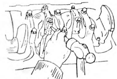
Fig.23. Knock out the connecting rod bearing bolts with a plastic hammer
- Place pieces of rubber or plastic hose onto the connecting rod studs (to protect the cylinder bore and pull out the connecting rods along with the pistons one by one from the cylinders. Immediately screw the bearing shells and bearing caps onto the corresponding connecting rods.
- After removal, arrange the pistons and connecting rods of both remaining units in order for installation.
- Hold the flywheel with a screwdriver inserted into the teeth from turning and unscrew the clutch mounting bolts evenly and crosswise.
- While continuing to hold the flywheel, remove the flywheel mounting bolts. Remove the flywheel. If necessary, tap with a plastic hammer.
- Remove the intermediate plate from the rear of the engine.
- Unscrew the rear oil seal flange. The oil seal can be immediately removed from the flange.
- Check and record crankshaft end play (Chapter 2.7.2).
- Remove the crankshaft. In the case of scrap, the bearing caps are numbered (No. 1 on the belt pulley side, No. 5 on the flywheel side). Remove the spacer washer from the middle bearing.
In Fig. Figure 24 shows an assembly diagram of the crank mechanism, which can be used during disassembly.
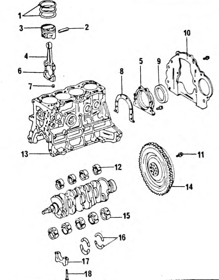
Pic. 24. Installation diagram of the cylinder block together with the crank mechanism. 1. Piston rings; 2. Piston pin; 3. Piston; 4. Connecting rod; 5. Oil seal flange; 6. Connecting rod bearing cover; 7. Nut 50 mm; 8. Flange gasket; 9. Rear oil seal; 10. Engine intermediate board; 11. Bolt 80 mm; 12. Connecting rod bearing shell; 13. Cylinder block; 14. Flywheel; 15. Crankshaft bearing; 16. Spacer washers 17. Main bearing cap; 18. Bolt 50 mm.
Disassembling the 3S FE engine
- Loosen the mounting plate of the generator V-belt, press the generator inward and remove the V-belt.
- Unscrew the water pump pulley.
- Remove the four spark plugs.
This requires an extended spark plug wrench to access the recessed spark plugs
- Unscrew the engine lifting brackets.
- Unscrew the exhaust manifold heat shield on one side of the engine, remove the two bolts and remove the manifold support.
- Unscrew the exhaust manifold. If there is another heat shield, remove it.
- Unscrew the ignition distributor mounting bolts, remove the ignition distributor and the sealing ring.
- Disconnect the water and vacuum hoses of the exhaust gas emission reduction system and unscrew the outlet fitting of the cooling system, which is shown in Fig. 25.
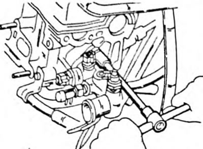
Fig.25. Unscrew the water outlet pipe at the indicated locations.
- Disconnect the water hoses from the bypass tube and unscrew the tube. Remove the O-ring.
- Unscrew the four cylinder head cover nuts and remove the cover. Remove the gasket and rubber tips
- Rotate the crankshaft until the mark on the crankshaft belt pulley coincides with the mark "0" on the scale on the front of the engine (see fig. 7). Check that the valves of the first cylinder are open. If they switch (one opens, the other closes), turn the crankshaft one more revolution. To avoid mistakes, keep an eye on the camshaft gear. There is a hole on the wheel that should coincide with the mark on the camshaft bearing cap, as shown in Fig. 26.
Pic. 26. Slowly rotate the camshaft sprocket until the hole (1) and the gear wheel will not be in line with the pointer (2) in the bearing cover.
- Remove the crankshaft pulley bolt (hold the flywheel from turning the crankshaft) and remove the pulley. To remove the pulley, you can use two pry bars. You can also use the puller shown in Fig. 8. The puller is installed in two threaded holes in the pulley.
- Unscrew the upper and lower toothed belt covers and remove the gaskets. Remove 5 bolts of the bottom cover and 4 bolts of the top cover.
- Remove the timing belt guide washer (see fig. 9).
- When installing the timing belt, again mark it with an arrow for the direction of movement of the belt and a mark for the position of the camshaft gear relative to the crankshaft gear, as shown in Fig. 27 and 28 for the camshaft and crankshaft gears.
Pic. 27. Before removing the toothed belt, mark the relative position marks on the toothed belt and camshaft gear (only when reinstalling the timing belt).

Pic. 28. Mark the direction of travel arrow on the timing belt (paint) and before removing the timing belt, place relative position marks on the timing belt and on the crankshaft gear.
- Loosen the toothed belt tensioner bolt at the front of the engine, press the tensioner to the left using a screwdriver, as shown in Fig. 11, and secure in the new position. The timing belt is now free and can be removed. If necessary, you can remove the belt tension roller.
- Remove the gear from the crankshaft. If necessary, use two screwdrivers or pry bars, as shown in Fig. 29.
Pic. 29. Removing the crankshaft gear using screwdrivers
- Remove the camshaft wheel bolt. Keep the shaft from turning while doing this. Typically, this is done by inserting the tool shown in Fig. into two holes in the wheel. 30, but you can also insert a long rod into one of the holes, turn the wheel until the rod stops in the cylinder head and then unscrew the bolt. Remove the washer and gear.
Pic. 30. Hold the camshaft gear from turning. The water pump wheel is also held in place.
- If installed, remove the exhaust gas return valve and control valve. They are located in the location shown in Fig. 31. To remove, disconnect the vacuum hoses, unscrew the union nut and unscrew the two bolts. Remove the control valve with gasket. The exhaust gas return valve is secured with one bolt.
Pic. 31. Location of exhaust gas return system valves.
- On an injection engine, unscrew the throttle valve block. Remove the cold engine starter injection pipe and the air supply pipe. It is secured with two bolts. Before doing this, disconnect the air hoses.
- Unscrew the intake manifold support bolts, remove the support, disconnect the vacuum hose and remove the six bolts and two nuts of the intake manifold. Remove the intake manifold with gasket.
- Remove the injection pipes and injectors.
- Before removing the camshafts, measure their axial play. To do this, install a dial indicator at the end of the camshaft, as shown in Fig. 32. Pull the shaft by the camshaft gear until it stops. Reset the dial indicator scale to zero, press the dipstick on the white rod and press the camshaft in the opposite direction. The intake camshaft play should be from 0.045 to 0.10 mm; The backlash of the exhaust distribution valve should be from 0.030 to 0.085 mm. If the shaft play exceeds the specified value, the shaft must be replaced. Sometimes it is necessary to replace the bearing caps and cylinder head together.
Pic. 32. Measuring the axial play of camshafts. The play of both shafts must be measured.
- Since the axial play of the camshafts is very small, the camshaft should be kept straight during removal to avoid damaging the cylinder head. For this reason, the following instructions must be followed precisely:
— Turn the intake camshaft until the pin on the sprocket is installed in the position shown in Fig. 33. When the pin is installed at a given angle before TDC, the cams of the second and fourth cylinders rest against the pushers and hold the camshaft in a horizontal position.
Pic. 33. Pin positions (1) when removing the exhaust manifold shaft
— Fasten both separate gears of the intake camshaft to each other by screwing an M6x bolt 16-20 mm long into the wheels, as shown in Fig. 34. This relieves the pressure of the torsion spring of the secondary gear. Before removing the camshaft, be sure to ensure that the spring is unloaded.
Pic. 34. Blocking of the exhaust camshaft drive gear. Before removing the shaft, the pressure of the installed spring must be compressed onto the gear, consisting of two parts. 1. Inserted bolt; 2. Main drive wheel; 3. Secondary drive wheel
— Unscrew the bolts of the rear bearing cover, cover No. 3 and cover No. 4 evenly and crosswise, and exactly in this sequence: rear bearing cover, cover No. 3 and cover No. 4. At this point, do not loosen the cover bolts No. 2.
Pic. 35. Sequence of loosening the bolts of the exhaust camshaft bearing caps. The cover indicated by the arrow does not go down.
— Unscrew the bolts of cover No. 2 evenly and crosswise. At the same time, constantly ensure that the camshaft remains in a straight and horizontal position. If it is impossible to remove the camshaft in a horizontal position, screw on the bearing cap No. 2, screw the remaining caps in the reverse order, check the position of the pin according to Figure 36 and repeat the work operations again. The shaft has a solid toothed pulley and cannot be disassembled.
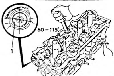
Fig.36. Pin position (1) when removing the intake camshaft
- Using a Torx wrench, unscrew the cylinder head bolts in the sequence shown in Fig. 19. Loosening the bolts in a different sequence may cause the cylinder head to become misaligned. Raise the cylinder head. If the head is firmly seated, insert a screwdriver in the place indicated in Fig. 20, between the protrusion of the motor block and the head, without damaging the surface. The head sits on pins.
- The remaining work related to disassembly is carried out in a manner similar to that described for the 1.6 liter engine. When removing the gear of a suitable pump, it must be held in the same way as shown in Fig. 30 for the camshaft.