
Valve springs
To ensure perfect control of valve springs, a spring tester must be used. If there is none, the used spring can be compared with a new spring. To do this, clamp two springs together one after another in a vice and slowly tighten the vice. If both springs compress equally, this is a sign that they have approximately the same tension. But if the old spring compresses significantly more than the new one, then this is a sign of fatigue and the springs must be replaced as a set. The free length of the spring can be measured with a caliper. Springs must have a certain length, which is given in the tables of sizes and adjustments. Place the springs one at a time on a smooth surface (glass plate) so that the closed turn is on the bottom side. Place a steel corner next to the spring. Measure the gap between the springs and the angle at the top (Pic. 46). The tolerance is different for each engine type. When the tolerance is exceeded, the spring becomes skewed.
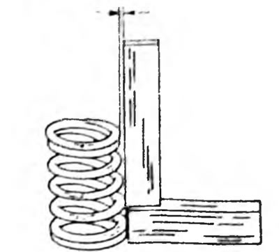
Fig.46. Check the misalignment of the valve springs using the specified method. The skew is measured between the arrows at the top (depending on motor type 2.0 or 2.5 mm)
Valve guides
Clean the guide bushings by pulling a rag soaked in gasoline through the guides in both directions. It is best to clean valve stems with a rotating wire brush, inserting it into the chuck of an electric drill and holding the valve stem close to it. Insert the valves one by one into the holes. To control the valve stem play in the holes, you must have a dial indicator and a caliper:
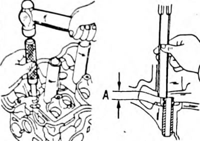
- Measure the inner diameter of the guide bushings with a dial indicator, as shown in Fig. 47. The result should be between 6.01 mm and 6.03 mm (on all engines).
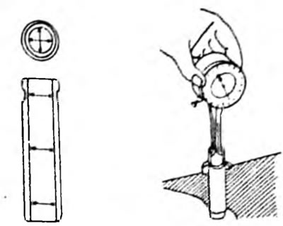
Pic. 47. Measuring the diameter of valve guides. On the left side of Fig. measurement locations are shown
- Measure the outer diameter of the valve stems in the three places and directions shown in Fig. 48. The nominal outer diameter of the exhaust valves is 5.965-5.980 mm, and the nominal outer diameter of the intake valves is 5.970-5.985 mm (on all engines).
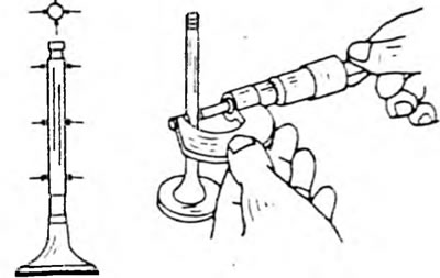
Pic. 48. Measuring the diameter of the valve stem. The measurement locations are shown on the left.
- Subtract the diameter of the valve stems from the inner diameter of the guide bushings. The result is valve stem play in the bores, which should not exceed 0.08 mm for intake valves and 0.10 mm for exhaust valves.
- Before replacing the guide bushing, check the general condition of the cylinder head. Cylinder heads with small cracks between the valve seats or between the valve seat and the first thread of the spark plug hole can be reinstalled and refinished as long as the cracks are no wider than 0.5mm. Also check the deformation of the cylinder head surface, which will be described below.
To replace the guide bushing, knock out the old bushing from the top side of the cylinder head. Before removing the guides, consider the following points:
- Heat the cylinder head to 80-100°C and knock out the old guide bushing from the top side into the combustion chamber. The drift must have a recess at the end that corresponds to the inner diameter of the guide bushing. So the poppy guide bushing should be knocked out at an angle, install the cylinder head as shown in Fig. 49.
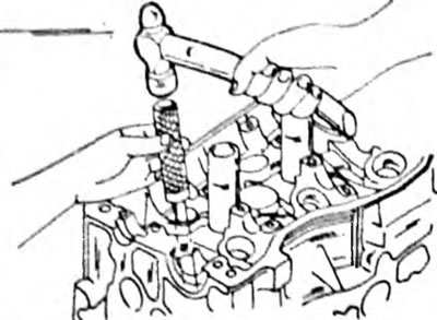
Pic. 49. Removing the valve guide using a special tool.
- Using a dial indicator, measure the inner diameter of the hole in the cylinder head. If the measurement result is between 11,000 mm and 11,027 mm, a bushing with a nominal outside diameter size can be installed. If the diameter exceeds 11.027 mm, a guide bushing with an increased outer diameter must be installed. This means that the holes for the guide bushings must be bored in the workshop. Do not press into holes with a larger outer diameter. When replacing valve guides, the valves are also replaced and the valve seats must be ground in. Clean the inner surfaces of the holes well, lubricate the new guides well and drive them from the camshaft side into the cylinder head, heated to 100°C, so that the upper end protrudes above the upper surface of the cylinder head by the size shown in Fig. 50, on a 1.6 liter engine 12.7-13.1 mm and on a 2.0 liter engine 8.2-8.4 mm.
Rome. 50. After pressing the valve guide, dimension A, indicated by arrows, must correspond to the values indicated in the text
When replacing the valve guide, mill the valve seat. If the valve seats cannot be ground in, the guide bushings should not be replaced.
Valve seats
Check valve seats for wear. Small signs of wear can be removed with a 45°cutter. But if there is significant wear, the valve seats must be milled again. The specified angles are shown in Fig. 51. Seat width applies to both types of engines. However, an angle must be provided to correct the height of the valve seat, that is, a 60°cutter should be used (1.6 l engine) or 75° (2.0 l engine). As mentioned, when installing new valves, the valve seats can be milled clean. First rout a 45°angle and then lightly use a 30°and 60°or 75°router bit on the top and bottom edge of the saddle to reduce the width of the saddle and bring it into the middle. The width of the seat working chamfer should be 1.0-1.4 mm for intake and exhaust valves. Modified seats must be ground in. To do this, apply grinding paste to the surface of the valve seat and insert the valve into the seat. Install a suction cup on the valve and turn the valve in different directions (Pic. 52). After grinding in, thoroughly clean all parts from paste and dirt and check the valve seat at the valve head and seat chamfer. The continuous matte ring characterizes the width of the valve seat and should be visible on both parts. Draw a few lines on the "ring" on the valve head. The lines must be drawn in a circle at a distance of 1 mm. After this, carefully lower the valve into the guide sleeve and seat and turn the valve 90°, pressing the valve (use a suction cup). Pull out the valve and check if the pencil marks have been removed from the chamfer. If the width of the valve seats is within the specified tolerances, the head can be reinstalled. Otherwise, process the valve seats or replace the head.
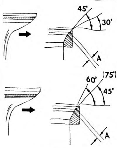
Pic. 51. Valve seat measurements Angles 30°, 75° (2.0 l engines) and 60° (1.6 l engines) are provided with corrective cutters. The dimension between the arrows is the width of the operating seat chamfer, the same for intake and exhaust valves.
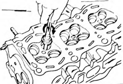
Pic. 52. Valve lapping
Valves
Minor damage to the surfaces of the valve plates can be eliminated by grinding the valves into the cylinder head seats, as described above. Measure the valves according to the data given in the size and adjustment tables, and replace any valves whose dimensions are out of tolerance. In this case, special attention should be paid to the length of the valves. All data is taken from size and adjustment tables. If the length is less than the minimum permissible, replace the valves. If the ends of the valve stems are worn, they can be ground on a grinder, as long as the correction requires removing no more than 0.50 mm of stem material and the resulting dimensions are within specified tolerances. The valve disc can be ground on a grinder, provided that the size between the arrows (pic. 53) will still be 0.5 mm if the valve can still be installed. Grind an angle of 44.5°on a grinder (The valve plate chamfer angle is less than the valve seat chamfer angle).
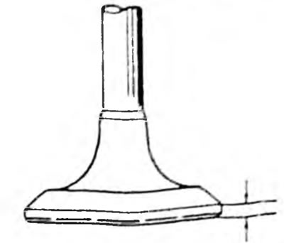
Pic. 53. The thickness of the edge of the valve head, which should not be less than the minimum permissible size
Cylinder head
Thoroughly clean the surfaces of the cylinder head and cylinder block and check for misalignment of the cylinder head surface. To do this, place a ruler on the head (pic. 54) Using feeler gauges, determine the gaps along, across and diagonally on the surface of the cylinder head. If a feeler gauge larger than 0.05 mm can be inserted, the cylinder head must be replaced. The same control should be carried out for the surface on which the collector is installed. Here also the permissible gap is 0.05 mm. In Fig. The 54 dashed lines indicate in which directions the measurements should be taken. Nowhere should the gap exceed the specified maximum value. The misalignment of surfaces in contact with the collectors should not exceed 0.1 mm.
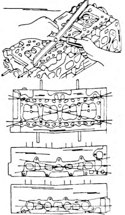
Pic. 54. Cylinder head surface measurements (above), intake manifold mounting surfaces (in the middle) and installation of the exhaust manifold (at the bottom).
Camshafts
Place the camshafts with the journals of the outer bearings into the prisms or clamp them in the centers of the lathe, as shown in Fig. 55, and install a dial indicator at one of the middle axles. Slowly turn the camshaft and take indicator readings. If during one revolution the needle deflection is more than 0.04 mm (on all engines), the camshaft needs to be replaced as it cannot be fixed. Check the integrity of the bearing journals and camshaft surfaces. If there is no external damage, measure the height of the cams and the bearing play:
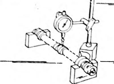
Fig.55. Measuring camshaft deflection
- Measure the height of the cams using a micrometer shown in Fig. 56. The specified dimensions and wear limits are given in the tables of dimensions and adjustments.
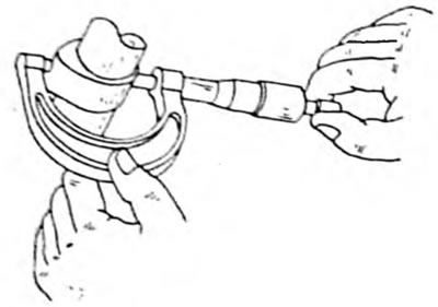
Pic. 56. Measuring the height of the cams with a micrometer
- Before checking bearing play, check for bearing metal peeling or cracking. If the covers are damaged, replace the covers, camshafts and cylinder heads.
- Clean the bearing caps and camshaft journals and arrange the caps according to bearing numbers.
- Bearing play is measured using a PLASTIGAGE plastic hair. Place a hair over the entire length of the trunnions (Pic. 57) and install the covers one by one. The arrow on all caps must point forward and the cap numbers must match the bearing numbers.
Pic. 57. Checking bearing play using a PLASTIGAGE hair. apply plastic hair (1) in the indicated position on the bearing journals. Measurement shown on 2.0L engine.
- Gently tap the covers with a hammer and insert the bolts. Tighten the bolts from the middle outwards to a tightening torque of 13 Nm (engine 4A-F/FE), or 19 Nm for the 3S-FE engine. Don't make mistakes. The camshaft must not be turned.
- Unscrew the bearing caps again and immediately check to see if there is a hair of PLASTIGAGE left on the cap. Otherwise, it also sticks to the bearing journals.
- Using the template from the PLASTIGAGE kit, measure the width of the crumpled plastic hair at the widest point (Pic. 58 or 59). It gives minimal bearing play. If the play is more than 0.10 mm, replace the cylinder head and/or camshaft.
Pic. 58. Checking the width of the PLASTIGAGE crumpled hair. Measurement shown on a 2.0 L engine
Pic. 59. Checking the width of the crumpled hair PLASTIGAGE. Measurement shown on a 1.6 l engine
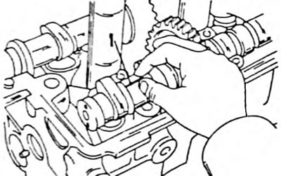
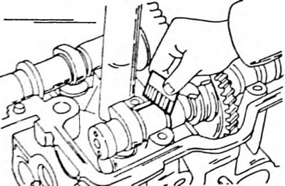
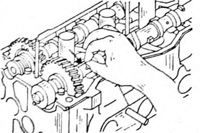
- Measurement of axial play of camshafts is carried out in accordance with the instructions given in the disassembly chapter (see also Fig. 32). If the play exceeds 0.25 mm (determined during disassembly), replace the camshaft and/or cylinder head. On both engines, the engagement play of both camshaft gears should be checked. To do this, insert the camshaft without the secondary gear and install the dial indicator, as shown in Fig. 60. Turn the indicated wheel in both directions and take readings from the dial indicator. If the play is greater than 0.30 mm, replace the camshafts.
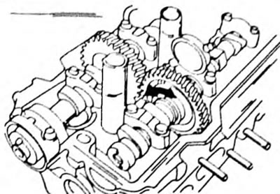
Pic. 60. Checking the meshing play between both gears and camshafts. Measurements are carried out identically on both engines
Toothed belt and gears
A belt with broken teeth must be replaced. Other defects include cracks, scuffs on the sides, or rounding of some or all of the wheels. In this case, the teeth of the gear wheels should also be checked. Hold the belt tensioner with one hand and turn the pulley with the other hand. If jamming occurs when turning the roller, replace the belt tensioner. The return spring of the tensioner must have a certain length. In this case, the length is measured between the inner sides of the spring hooks. On a 1.6 liter engine, the spring length should be 43.3 mm; on a 2.0L engine, the spring length should be 46.1 mm. If the spring is stretched, install a new spring.
Valve tappets
Measure the inner diameter of the holes for the pushers in the cylinder head and the outer diameter of the pushers. To do this you need to have an internal and a regular micrometer. The difference in size should be no more than 0.10 mm (1.6 l engine), or 0.07 mm (2.0 l engine). Otherwise, the pushers must be replaced, and in the worst case, the cylinder head.