
Engine 4A-F/FE
- Place a new cylinder head gasket on the cylinder block. Both centering pins should go through the gasket.
- Place the cylinder head on the cylinder block.
- Apply engine oil to the threads and the underside of the cylinder head bolt heads.
- Using a special wrench, tighten the cylinder head bolts in the reverse order shown in Figure 19 in three passes to a tightening torque of 60 Nm.
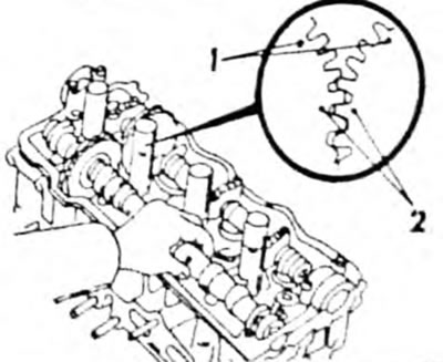
- Clamp the intake camshaft hexagon in a vice. and install all the parts shown in Figure 45 on the shaft. Install the retaining ring as shown in Figure 62.
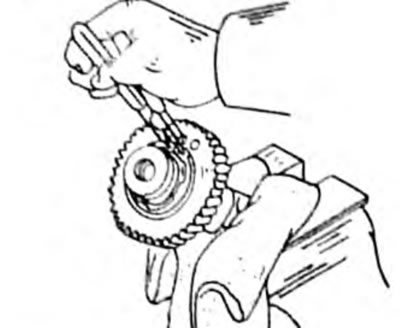
Pic. 62. Fastening parts on the intake camshaft, engine 4A-F/FE
- In accordance with Figure 43, insert the bolts (1) And (2) into the holes of the secondary gear and turn the wheel with a screwdriver so that the bolt can be inserted (3) into both gears and fix them in this position. Do not damage the camshaft.
- Install the exhaust camshaft into the bearing holes and rotate it to the position shown in Figure 63. In this position, the cams of the first and third cylinders press the pushers.
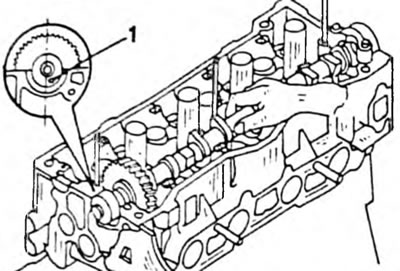
Pic. 63. Installation of the camshaft on the 4A-F/FE engine. Pin (1) must be in the specified position.
- Apply sealant to the surfaces under the bearing caps on the timing belt side.
- Place 4 bearing caps in accordance with Figure 64 on the camshaft in the cylinder head. Observe the directions of the arrows on the covers.
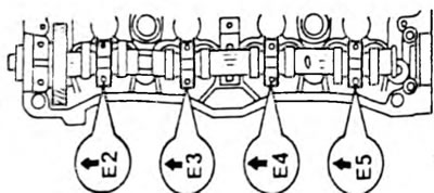
Pic. 64. Location of bearing caps on the 4A-F/FE engine. Arrows must point forward. Exhaust camshaft shown.
- Tighten all bearing cap bolts one by one from the center outwards to a tightening torque of 13 Nm.
- Lubricate the lips of the new oil seal and press the oil seal into the cylinder head without damaging the oil seal.
- After this, rotate the camshaft until the pin shown on the left in Figure 63 is installed. In this position, the cams of the fourth cylinder press the pushers.
- Install the intake camshaft into the cylinder head. At the same time, align the marks shown in Figure 65 and engage both gears. In this position, the cams of the first and third cylinders press the pushers.
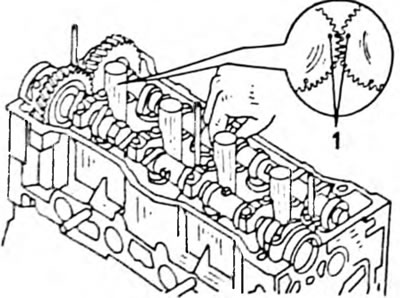
Pic. 65. Installation of the intake camshaft. Combine both marks ("1" in a mug).
- Lubricate the camshaft bearings.
- Place the bearing caps in accordance with their markings (see fig. 63) and tighten the bolts. Do not install bearing cap #1 yet. Tighten all bearing cap bolts one by one from the center outwards to a tightening torque of 13 Nm.
- Remove the bolt previously inserted to hold the drive gear in place.
- Install bearing cap No. 1. If there is difficulty, press the camshaft gear back and insert a screwdriver between the wheel and the cylinder head. Tighten both bolts alternately to 13 Nm.
- Using the method shown in Figure 66, rotate the camshaft one revolution from the TDC position again to the TDC position so that the pin is in the position shown in the figure. After installing the gears in their original position, check the alignment of the marks in accordance with Figure 67.
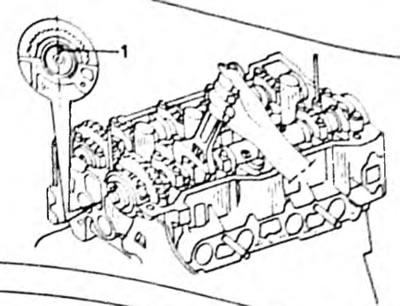
Pic. 66. Rotating the camshaft to install the pin (1)
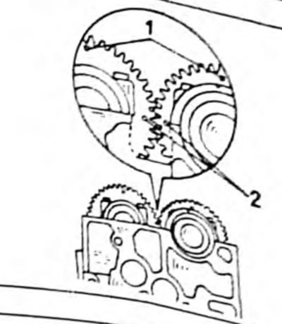
Fig.67. When installed correctly, the ignition timing marks should be in the indicated position. 1. Installation mark; 2. TDC mark
- Align the camshaft gear with the pin and place it on the camshaft in the manner shown in Figure 68. Hold the camshaft from turning and tighten the gear bolt to a torque of 47 Nm.
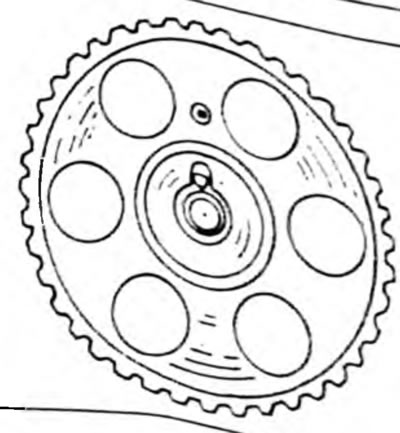
Pic. 68. Installation of the camshaft gear.
The timing belt can now be installed according to the following instructions:
- Check that the mark on the camshaft bearing cap matches the small hole in the gear (see fig. 68) and place the timing belt on the gear wheel so that the marks made when removing the belt match. Do not allow the belt to come off the crankshaft wheel.
- Loosen the bolt of the timing belt tensioner roller in accordance with Figure 69 and turn the crankshaft two turns from the TDC position to the TDC position. Only turn the crankshaft to the right.
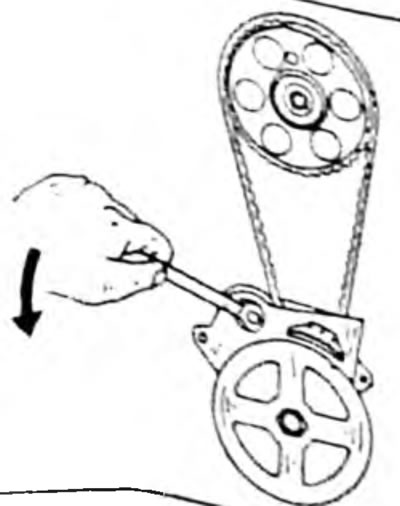
Pic. 69. Loosen the bolt of the timing belt tensioner roller (in the direction of the arrow).
- Check the valve timing in accordance with Figure 70. If the marks do not match, remove the timing belt and move it by one or two teeth.
Pic. 70. Alignment of marks on the camshaft and on the crankshaft pulley
- Align the camshaft gear with the pin and place it on the camshaft in the manner shown in Figure 68. Hold the camshaft from turning and tighten the gear bolt to a torque of 47 Nm.
- Tighten the tension roller bolt in Figure 69 with a tightening torque of 37 Nm.
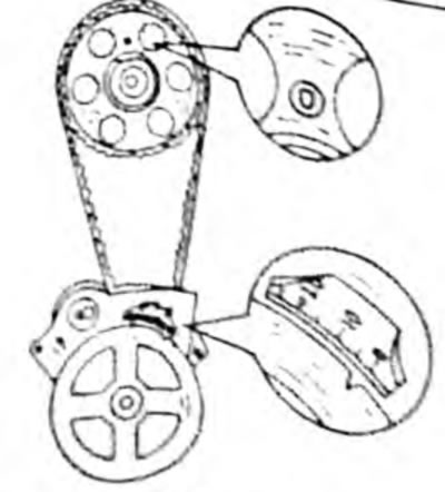
- Check the tension of the timing belt in the place indicated in Figure 71. If the belt does not bend to the specified size, it is necessary to adjust the tension roller.
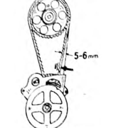
Fig. 71. Determine the toothed belt tension at the indicated location
- Check valve clearances as described in the next chapter.
- Install the timing belt cover.
- Clean the places indicated in Figure 72 from sealant and apply sealant with a brush.
Pic. 72. Rotate the intake camshaft until the pin is installed (1) to a position of 80°before TDC, that is, vertically.
- Apply the gasket and install the cylinder head cover. Secure the cylinder head cover with rubber tips and nuts.
- Screw in the spark plugs and tighten them to 18 Nm.
- Install the drive belt and water pump pulleys. Adjust the belt tension as described in Chapter 4.3.2.
- Install the intake manifold with a new gasket. Tighten the bolts and nuts with a tightening torque of 19 Nm. Install the intake manifold support. Tighten the upper bolt to a torque of 19 Nm, and the lower bolt to a torque of 40 Nm.
- Connect the water hose and crankcase ventilation valve.
- Install the fuel pump with two new gaskets and an insulating flange and tighten both bolts (carburetor engine).
- Apply a layer of sealant with a thickness of 2 to 3 mm to the well-cleaned surface of the filling device body. A special sealant is used here, which is available at the TOYOTA service station. Do not allow sealant to get into the holes. The housing should be installed in 15 minutes. Otherwise you will have to reapply the sealant. The bolts are tightened to a torque of 20 Nm. Connect both water hoses.
- Install the ignition distributor.
- Install exhaust manifold (new gasket. Tighten the bolts and nuts to 25 Nm. Install the upper heat shield and manifold support.
- Install the drain pipe in the same way. Tighten the bolts to 20 Nm.
Engine 3S-FE
- Place a new cylinder head gasket on the cylinder block. Both centering pins should go through the gasket. Check the position of the gasket.
- Place the cylinder head on the cylinder block.
- Apply engine oil to the threads and underside of the heads of all cylinder head bolts.
- Using a special wrench, tighten the cylinder head bolts in the reverse order shown (pic. 19) three passes before the final tightening torque of 65 Nm.
- Clamp the hexagon» body of the intake valve shaft in a vice and install all the parts indicated in Figure 45 on the shaft. Install the retaining ring as shown in Figure 62.
- In accordance with Figure 44, insert the bolt (1) into the hole of the secondary gear and turn the wheel with a screwdriver so that the bolt can be inserted (2) into both gears to fix them in this position. Do not damage the camshaft.
- Place the exhaust camshaft into the bearing holes and rotate it to the position shown in Figure 73. In this position, the cams of the first and third cylinders press the pushers.
Pic. 73. Rotate the intake camshaft. Pin (1) must be in the TDC position, that is, vertically.
- Apply a layer of sealant 2-3 mm thick on the surfaces of the front bearing cover in accordance with Figure 74.
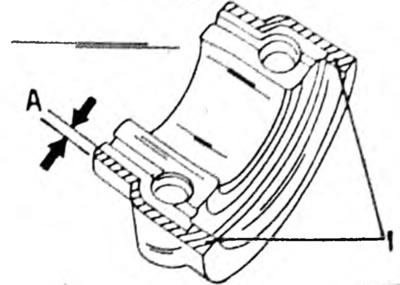
Pic. 74. In places (1) apply thick sealant "A" 2-3 mm
- Place 4 camshaft bearing caps in accordance with Figure 75 on the camshaft in the cylinder head. Also install the front bearing cover on the toothed belt side. Observe the directions of the arrows on the covers.
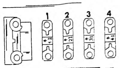
Pic. 75. Position of bearing caps. The rear exhaust camshaft bearing cap looks different. The covers are marked either I" and number (intake camshaft), or E" and number (exhaust camshaft).
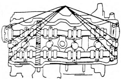
- Tighten all the bearing cap bolts one by one from the center outwards in the sequence shown in Figure 76 to a tightening torque of 19 Nm.
Pic. 76. Sequence of tightening the intake camshaft bearings with the roof. The intake camshaft bearing caps are tightened in a mirror image.
- Lubricate the lips of the new oil seal and press the oil seal into the cylinder head without damaging the oil seal.
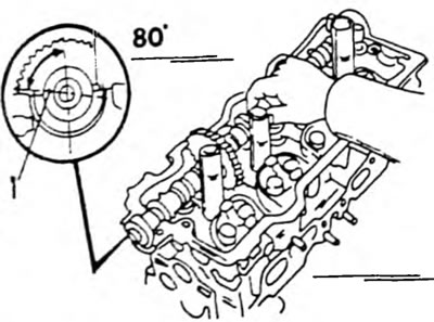
- After this, rotate the camshaft so that the pin shown in Figure 77 is in position 10 before TDC.
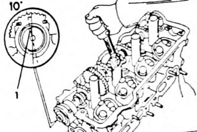
Pic. 77. Before installing the exhaust camshaft, the intake valve camshaft must be brought to the specified position. Important position (1).
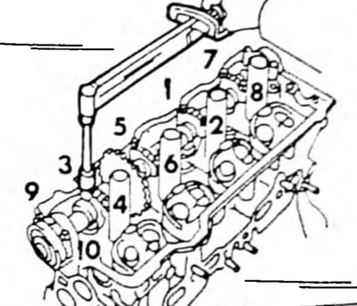
- Install the intake camshaft into the cylinder head. At the same time, align both marks shown in Figure 78 and engage both gears. In this position, the cams of the first and third cylinders press the corresponding pushers. It should be taken into account that there are several marks on the camshaft gears, that is, the necessary marks should be combined. The figure shows how the marks should be positioned after installation. At the same time, slowly rotate the exhaust camshaft with the gears engaged. In this case, slowly turn the intake camshaft step by step to the left or right until the exhaust camshaft fits into the bearing holes without protruding.
- Lubricate the camshaft bearing areas as well as the threaded parts and the undersides of the bolt heads.
- Place the bearing caps in accordance with their markings (same as shown in Figure 75 for intake camshaft) and screw in the bolts of the bearing caps in accordance with Fig. 76, but in a mirror image, that is, for this shaft, the bearing cap bolts on the front side are tightened last. The tightening torque is 19 Nm. All bearing caps must be marked "E". Otherwise, the wrong cover was installed on the intake camshaft.
- Remove the bolt inserted to lock the drive gear.
- Rotate the camshaft one revolution from the TDC position again to the TDC position so that the marks coincide again, as shown in Figure 78 after installing the gears in their original position.
Pic. 78. Correct mark matching (2). Do not confuse them with dot marks (1).
- Align the camshaft gear with the pin and place it on the camshaft. The marks shown in Figure 26 should be located at the top. Hold the camshaft and tighten the gear bolt to a torque of 54 Nm.
Now install and tension the timing belt according to the following instructions:
- Place the toothed belt on the toothed wheel so that the marks made when removing the belt match. Do not allow the belt to come off the crankshaft wheel. The belt must be tensioned between the places indicated by the arrows in Figure 79.
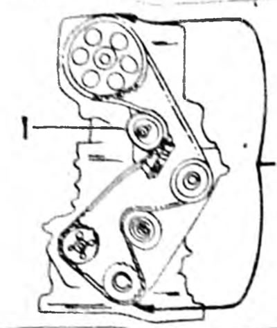
Pic. 79. Correctly installed timing belt. Tension roller (1) serves to tension the belt
- Loosen the timing belt tensioner pulley bolt (this is the top roller in figure 79) and turn the crankshaft two turns from the TDC position to the TDC position. Turn the crankshaft clockwise only.
- Check the marks on the camshaft gear again and tighten the toothed belt tensioner bolt to a torque of 42 Nm. If the marks do not match, remove the timing belt and re-install it without disengaging it from the crankshaft gear. When installing a removed belt, the marks made during removal must match.
- Check the tension of the toothed belt in the place indicated in Figure 80. If the belt is tensioned in this place, the adjustment has been made correctly. Otherwise, the tension should be adjusted by loosening and tightening the tensioner bolt. When tightening the bolt, hold the tension roller in the new position.
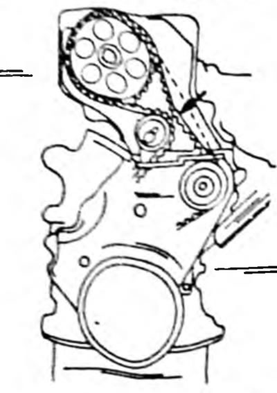
Pic. 80. Press the timing belt in the direction of the arrow. If the belt is pushed to the belt on the opposite side, then the tension is correct
- Check and adjust the valve clearances and install the timing belt cover.
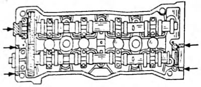
- Clean the places indicated in Figure 81 from sealant and apply sealant. Place the gasket on the cylinder head cover and install the cylinder head cover. Secure the cylinder head cover with rubber tips and nuts in accordance with Figure 82. First insert the tips at the indicated angle and then install them in their original position.
Pic. 81. Apply sealant in the indicated areas
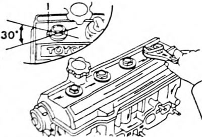
Pic. 82. Installing the cylinder head cover. Rubber tips must be inserted with markings (1), as it shown on the picture
- Screw in the spark plugs and tighten them to 18 Nm.
- Install the intake manifold with a new gasket. Tighten the bolts and nuts with a tightening torque of 19 Nm. Install the intake manifold support. Tighten the upper bolt to a torque of 19 Nm, and the lower bolt to a torque of 40 Nm.
- Install the air pipe on the two bolts and connect the air hoses. Also install the cold start pressure pipes, throttle body and exhaust gas return device parts. Connect all vacuum hoses.
- Install a new O-ring on the drain pipe, lubricate the ring with engine oil and install the pipe with a new gasket. Tighten the tube (two nuts and bolts) torque 9 Nm.
- Remove the old sealant from the coolant drain fitting and apply new sealant to the surface of the housing. Connect the water and vacuum hoses.
- Install the ignition distributor.
- Install the exhaust manifold with a new gasket, heat shield, etc.
- Install the alternator and adjust the V-belt tension as described in chapter "Electrical equipment".