
Speed sensors (VSS) ABS systems
Note. The following procedure is carried out on a moving vehicle, putting the system in diagnostic mode. In this case, the ABS system will not work, only the normal brake system will work.
1. Turn the ignition key to the OFF position. Check battery voltage. It should not be lower than 12V.
2. With the ignition on, make sure that the ABS warning lamp on the instrument panel flashes for 3 seconds and goes out. Turn the ignition key to the OFF position.
3. Connect all three terminals Tc, Ts and E1 on the DLC1 connector with jumpers.
4. Apply the parking brake and start the engine without depressing the brake pedal. Pressing the pedal will either cancel the check or enter an incorrect DTC.
5. The control lamp on the instrument panel should light up 4 times per second. If the control lamp indicates a malfunction code, the malfunction must be corrected and its code cleared before continuing with the test. If the lamp does not light up, check the condition of the brake light sensor on the brake pedal, the DLC1 connector and its wiring to the ABS ECU.
6. To check the signal level of the sensor, release the parking brake and drive straight at low speed. When reaching a speed of 3 - 8 km / h, the lamp should go out. When it goes out, the lamp will start flashing again if the vehicle speed goes beyond the specified limits. This indicates that the system is functioning normally. If there are no flashes, the system is faulty.
7. Check the signal change by driving onto the road. When the speed reaches 40–50 km/h, after a second pause, the lamp should light up. As before, when you leave this speed range, the lamp should go out. Otherwise, the system is faulty.
Note. When the lamp goes out, do not subject the car to sudden acceleration and braking.
8. Stop the vehicle in a safe place and fully apply the parking handbrake. Read the fault codes registered by the system.
9. Turn the ignition key to the OFF position and remove the jumper from the DLC1 connector.
Checking sensors
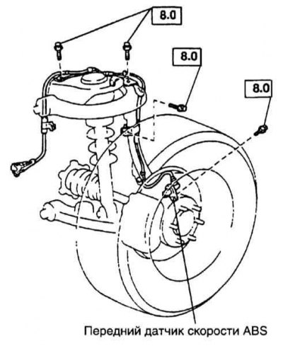
Front VSS ABS
Rear VSS ABS
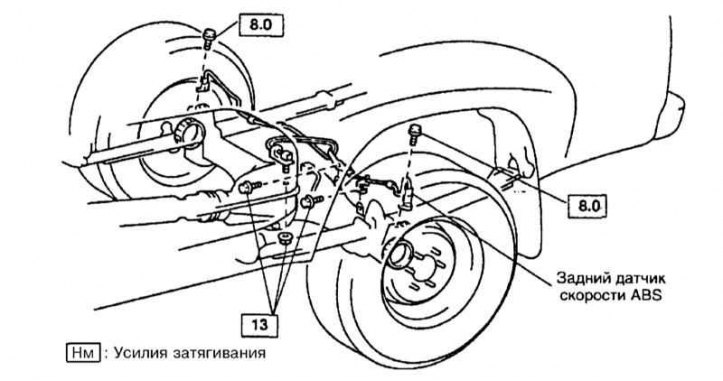
1. Disconnect the ABS wheel sensor connector (refer to the illustrations above).
2. Measure the resistance between terminals 1 and 2. It should be 0.97 - 1.77 kOhm for the front and 0.5 - 1.6 kOhm for the rear sensor.
3. If the resistance is not as specified, replace the sensor.
4. Check for short circuit between terminals and case. If the insulation is broken, replace the sensor.
5. Connect the sensor wiring connector.
6. Check sensor installation. Tighten the loose fastening bolt with a force of 8 Nm.
7. Remove hub with rotor. Check for damage to the rotor teeth. If necessary, replace the rotor.
Note. To avoid damage, do not hit the rotor and hub with a hammer.
Removal and installation
1. Disconnect the sensor wiring from the block and give the bolts of the wiring clamps to the frame, upper arm and steering knuckle (front sensor) or fuel tank (rear sensor).
Note. Throw away the old fasteners.
2. Remove the sensor.
3. Installation is carried out in the reverse order. Tighten the sensor fasteners and wiring to the required torque.
Checking the deceleration sensor
Note. The procedure described below is carried out with a stationary vehicle, putting the system into diagnostic mode. In this case, the ABS system will not work, only the normal brake system will work.
1. Turn the ignition key to the OFF position. Check the voltage at the battery terminals, which should not be lower than 12V.
2. Turn on the ignition. Make sure the ABS warning light comes on for a couple of seconds and goes out. Turn the ignition key to the OFF position.
3. Use a jumper to short the terminals E1 and Ts of the DLC1 connector.
4. Fully apply the parking brake, depress the brake pedal and start the engine.
5. After a while, the ABS warning lamp should flash at 4 flashes per second.
6. Accelerate the vehicle on a level road to a speed of at least 45 km/h. If the system is working properly, the control lamp should go out.
7. After stopping the car, the control lamp should flash. Connect the terminals Tc and E1 of the DLC1 connector with a jumper and count the number of flashes of the ABS lamp.
8. If the lamp lights up more than twice per second, then the first fault code is present.
9. Turn the ignition key to the OFF position. Troubleshoot.
10. Remove jumpers from conclusions of a diagnostic socket.
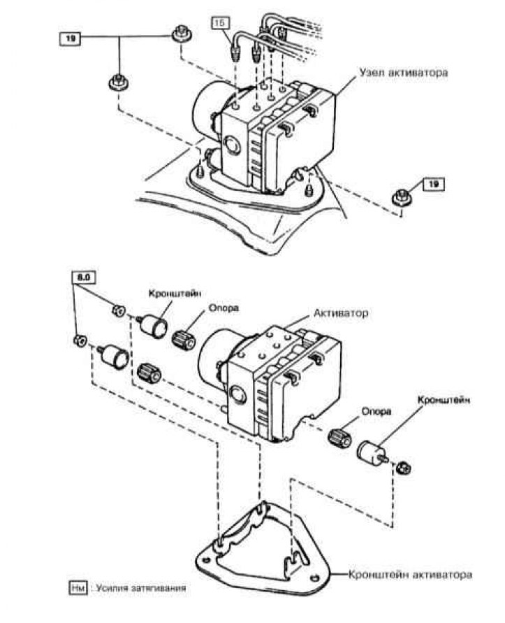
Removal and installation of the activator
ABS activator
Activator installed on the ABS ECU
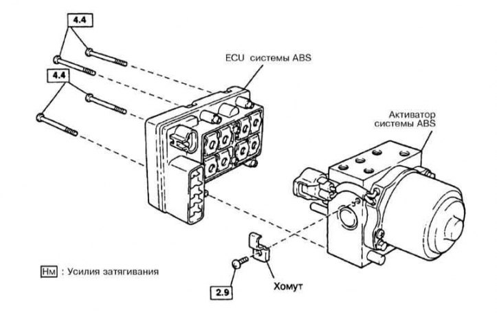
1. Disconnect the brake pipes and plug them. Disconnect the ABS connector from the activator (refer to the illustrations above).
2. Give bolts and nuts of fastening and remove the activator from the car.
3. Remove the unit from the bracket.
4. Installation is carried out in the reverse order. Tighten fasteners to the required torque.