
Location of ABS units
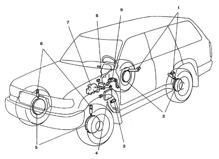
1. Rear speed sensors; 2, 5. Speed sensor rotors; 3. Stop signal switch; 4. Control unit; 6. Front speed sensors; 7. Actuator; 8. Relay; 9. Deceleration sensor
Actuator
The actuator consists of a master cylinder, an electro-hydraulic pump and 4 solenoid valves.
The pump is designed to pump fluid into the actuator receivers, through which pressure is supplied to the brake circuit.
The valves control the pressure in the brake circuit when the ABS system is activated, there is 1 valve per wheel.
Wheel speed sensors
Rotary type sensors mounted on each of the wheels. The signals from the sensors are sent to the control unit.
The front sensors are mounted on the steering knuckle, next to the toothed rings of the rotors. The rotors are structurally integrated with the front axle shafts.
The rear sensors are mounted on the axle beam, the rotors are part of the rear hub.
ABS control unit
The control unit is mounted under the front bulkhead of the body. The block receives signals from the brake light switch and speed sensors of each wheel, on the basis of which the pressure in the hydraulic drive of this wheel is regulated. The control unit also has the function of self-diagnosis and failure storage.
If the system fails, the control lamp on the instrument panel lights up, and a failure code is stored in the memory, which can be read and the nature of the malfunction determined.