Company Honda Company Ford Company Skoda Company Kia Company Mazda Company Mercedes Company Renault
English Русский
Български
Беларускі
Український
Српски
Hrvatski
Română
Polski
Slovenský
Magyar
Bookmark Articles Sitemap Contacts
ToyotaMan.ru


Camry Corolla Corona Carina Land Cruiser Highlander 4Runner RAV4 Others
Cruiser 100 (1998-2007) Cruiser 60/80 (1980-1997, petrol) Cruiser 70 (1985-1996, diesel)

Brake Master Cylinder — Removal, Disassembly and Installation [Toyota Land Cruiser J60]

  • Main
  • Land Cruiser
  • J60 (1980-1997)
  • Chassis, running gear
  • Brake system
  • Brake Master Cylinder — Removal, Disassembly and Installation
0
Contents: Removal ↓ Disassembly ↓ Installation ↓

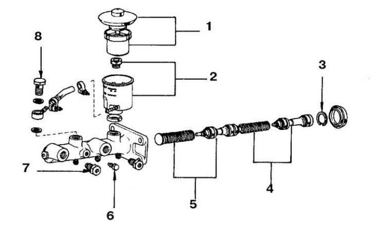
Small reservoir brake master cylinder parts


1. Cork and mesh filter; 2. Tank; 3. Retaining ring; 4. Primary piston with spring; 5. Secondary piston with spring; 6. Lock bolt; 7. Plug; 8. Fitting


Large reservoir brake master cylinder parts
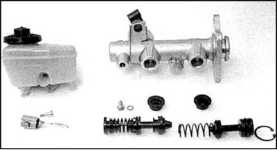


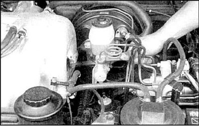
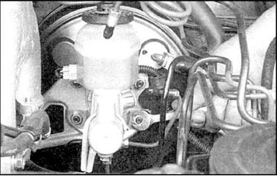
The brake master cylinder is mounted in the engine compartment on a vacuum booster.

Removal


1. Use a syringe to remove some of the liquid from the tank.

2. Place a tray or a rag under the cylinder.


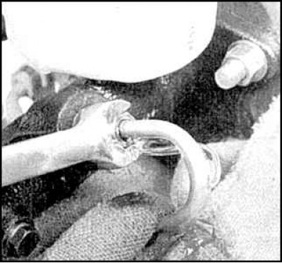
3. Loosen the hose fittings on the master cylinder.


4. Disconnect and plug the tubes.


5. Disconnect the connector from the tank (if provided), unscrew the 2 nuts securing the cylinder to the vacuum booster and remove the cylinder.

Disassembly


Cylinders with a large or small tank are installed on cars; the procedures for disassembling and assembling these units are almost the same, with the exception of reservations.

Before disassembling, purchase a cylinder repair kit.


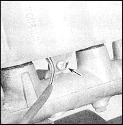
1. On the cylinder with the small tank, unscrew the tank mounting bolt.


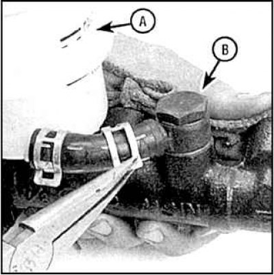
2. Loosen the tank clamps (A) and the fitting (B) and remove the tank.


3. On the cylinder with the large tank, unscrew the screw and remove the tank.


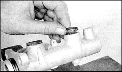
4. Check the condition of the gasket.
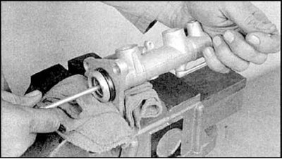


5. Clamp the cylinder in a vice, press the pistons and unscrew the lock bolt. Replace the bolt gasket.


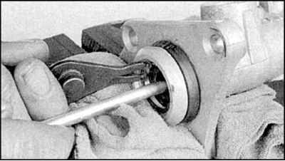
6. Press the pistons back again and remove the snap ring.


7. Disassemble the cylinder, paying attention to the order of installation of the parts.
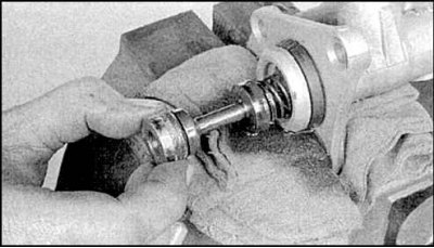


8. Remove the primary piston.
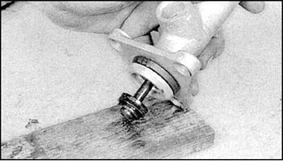


9. Remove the secondary piston by tapping it on a block, being careful not to tilt it, otherwise the cylinder will be scratched.

10. Pay special attention to the springs, which differ for different pistons.

11. Check the condition of the cylinder.

12. If scratches or discolored areas are found, replace the cylinder. Honing the cylinder is prohibited.

13. Replace all parts, installing new ones from the repair kit in the same order. Before assembly, dip the parts in brake fluid.

14. Assemble the pistons, insert them into the cylinder, press them back and tighten the lock bolt.

15. Install the new retaining ring, making sure that the ring fits into the groove.


16. Install the tank gaskets and tank.

17. When installing, fill the cylinder with liquid.

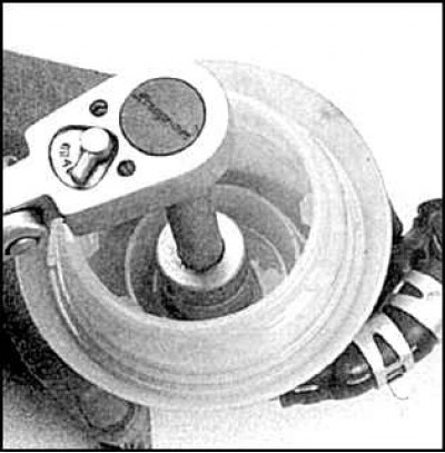
18. Clamp the cylinder in a vice by the flange, fill the tank with fluid, tighten the plugs and press on the piston with a large Phillips screwdriver.

19. Unscrew the plug to let the air out.

20. Screw the plug back on and release the piston.

21. Repeat these steps until liquid starts to come out of the hole under the nipple. Maintain the liquid level in the tank at all times.

22. Repeat the air removal steps for the other hole.

23. Instead of a plug, you can close the hole with your finger.

24. Release your finger after pressing the pistons, after the liquid flows out, close the hole with your finger and release the pistons.

25. After a few seconds, press the plunger again and remove your finger.

26. Repeat the procedure and do the same on the other hole.

27. Once only liquid starts flowing out of the holes, tighten the plugs.

Installation


1. Place the cylinder back in place and tighten the nuts by hand.

2. Screw in the fittings without distortion, manipulating the cylinder.

3. Tighten the nuts and fittings.

4. Add liquid to the tank up to the upper mark and tighten the cap.

5. You can also remove air from the cylinder on a car, working together. To do this, ask your assistant to press the pedal and hold it.

6. Unscrew the nipple and release the air.

7. Tighten the nipple and ask your assistant to release the pedal.


8. Continue until liquid begins to flow out of the cylinder.
This article is available at: russian, bulgarian, belarusian, ukrainian, serbian, croatian, romanian, polish, slovak, hungarian
The article material has been checked: Evdokimov Evgeniy
Share information:
◀ Previous
Cruiser 60/80: Brake system
Next ▶

Wheel brake cylinder — removal and disassembly
Replacing drum brake shoes
Brake disc — inspection, removal and installation
Brake Caliper — Removal, Disassembly and Installation
Replacing disc brake pads (front or rear)
Hydraulic Hoses and Tubes — Replacement
Bleeding the brake hydraulic system
Vacuum brake booster — removal, inspection and installation
Rear disc brake handbrake pads
Adjusting the handbrake
Similar articles on other Toyota models

➥ Brake Master Cylinder — Removal and Installation Toyota Camry XV20 (1996-2001)
➥ Installing the master brake cylinder Toyota Corona T190 (1992-1997)
➥ Master brake cylinder — device Toyota Carina T190 (1992-1996)
➥ Brake Master Cylinder — Removal and Installation Toyota 4Runner N120 (1989-1995)
➥ Replacing the brake master cylinder Toyota RAV 4 XA10 (1994-2000)
➥ Master brake cylinder Toyota Duet (1998-2004)
Link in different formats to this article
Comments and feedback from visitors
No comments yet


Add two numbers 31 + 13


Cruiser 100 (1998-2007) 
  • General information
  • Introduction to the guide
  • Controls and instruments
  • Maintenance
  • Power unit
  • Petrol engines
  • Diesel engines
  • Cooling and heating
  • Power and exhaust systems
  • Engine electrical equipment
  • Engine management systems
  • Transmission
  • Automatic gearbox
  • Transmission line
  • Chassis, running gear
  • Brake system
  • Car suspension
  • Steering
  • Body and interior
  • Exterior (external elements)
  • Interior (internal elements)
  • Doors, locks and windows
  • Electrical equipment
  • Equipment and devices
  • Electrical circuits
Cruiser 60/80 (1980-1997, petrol) 
  • General information
  • User manual
  • Maintenance
  • Power unit
  • Petrol engines 2F and 3F-E
  • Petrol engines 1FZ-FE
  • Engine overhaul
  • Engine electrical equipment
  • Cooling and heating
  • Fuel system (carburetor)
  • Fuel system (injector)
  • Toxicity reduction system
  • Transmission
  • Car gearbox
  • Clutch
  • Transfer case
  • Drive shafts and axles
  • Chassis, running gear
  • Brake system
  • Car suspension
  • Steering
  • Body and interior
  • Exterior and interior
  • Doors, locks and windows
  • Electrical equipment
  • Equipment and devices
  • Electrical circuits
Cruiser 70 (1985-1996, diesel) 
  • General information
  • User manual
  • Maintenance
  • Power unit
  • Engine adjustment
  • Engine repair
  • Fuel system
  • Control system
  • Turbocharging system
  • Cooling and lubrication system
  • Charge and start system
  • Transmission
  • Clutch
  • Mechanical gearbox
  • Automatic gearbox
  • Transfer case
  • Chassis, running gear
  • Car suspension
  • Brake system
  • Steering
  • Body and interior
  • Body elements
  • Heating and air conditioning
  • Electrical equipment
  • Equipment and devices
  • Electrical circuits
ToyotaMan.ru © 2018–2026 • Mobile version • Interesting about Toyota • Administration • Sitemap: EN BG BY UA RS HR RO PL SK HU • Search system • Bookmark
Camry Vista-V40 • Camry XV10 • Camry XV20 • Camry XV30 • Corolla Verso-AR10 • Corolla E80 • Corona T190 • Carina T170 • Carina T190 • Land Cruiser J70 (diesel) • Land Cruiser J60 (petrol) • Land Cruiser J100 • Highlander XU20 (petrol) • 4Runner N120 • RAV4 XA10 • RAV4 XA20 • Duet M100 • Dyna Y50 •
We require cookies to enable some interactive features. Is that ok with you?