
FJ60, 62 steering gear parts
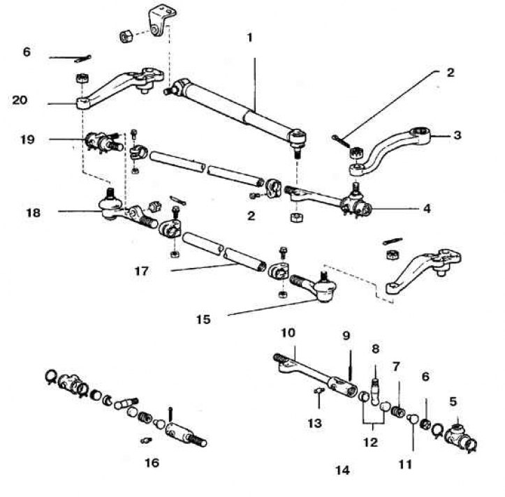
1. Vibration damper; 2. Cotter pin; 3. Bipod; 4, 19. Leading rod tip; 5. Case; 6. Plug; 7. Spring; 8. Ball pin of the rod end; 9. Cotter pin; 10. Leading rod end; 11. Saddle; 12. Ball pin inserts; 13. Oil can; 14. From the side of the bipod; 15, 18. The tip of the driven thrust; 16. From the side of the driven thrust; 17. Driven traction; 20. Steering arm
FJ80 Steering Parts
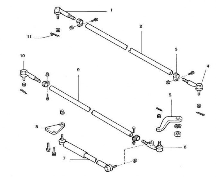
1, 4, 6, 10. Leading rod tip; 2. Traction; 3. Collar; 5. Bipod; 7. Vibration damper; 8. Bracket; 9. Leading rod; 11. Cotter pin
Examination
1. The rotation of the wheels is ensured by the transfer of force from the rudder gearbox through the bipod, tie rods and tie rod ends. Parallel to the bipod of the steering wheel, a steering wheel vibration damper is attached.
2. Set the wheels to the straight ahead position and lock the steering wheel.
3. Raise the vehicle so that the wheel is about 2.5 cm off the ground.
4. Check the play in the tie rod ends. To do this, install the indicator so that its leg rests on the edge of the wheel. Slightly shake the wheel in a horizontal plane. If the indicator reading exceeds 6 mm, then it is necessary to check the condition of all tie rod ends and replace worn parts.
5. Raise the front of the vehicle and check the condition of the tie rod ends and tie rod boots, as well as the jamming swivel joints.
Removal and installation
Drawbar ends
1. Remove the wheel.
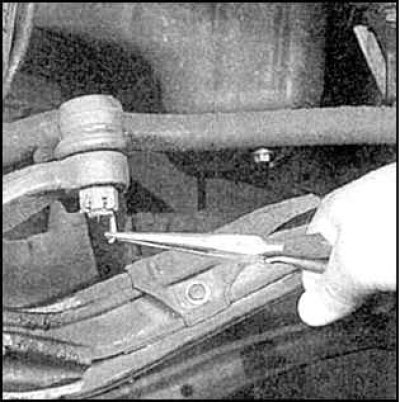
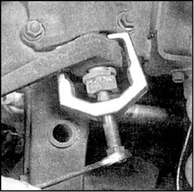
2. Loosen and loosen the castle nut of the ball joint, do not completely loosen the nut.
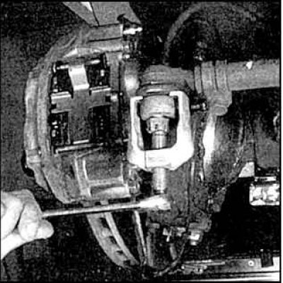
3. Using a puller, press the hinge pin out of the eye of the steering knuckle arm.
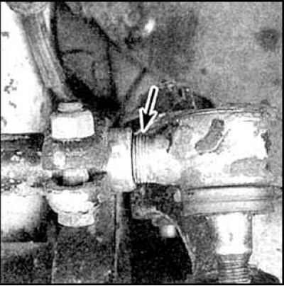
4. When replacing the tip, count the number of threads (arrow), on which the tip is wrapped. Release the clamp and unscrew the tip.
5. Lubricate the threaded part of the tip with grease and wrap it in a rod so that the end of the tip is separated from the rod by the number of threads determined before removal. Do not tighten the clamp.
6. Insert your finger into the eye of the lever and tighten the nut. The finger should fit snugly into the eye. If the pin rotates in the lever eye when the nut is tightened, push it into the taper hole.
7. Replace the cotter pin, if necessary tighten the nut until the groove of the nut coincides with the hole for the cotter pin in the threaded part of the pin.
Attention! It is forbidden to unscrew the nut in order to ensure the free passage of the cotter pin.
8. Tighten the clamp nuts.
9. Install the wheel and lower the car.
Leading rod
1. Raise one side of the car.
2. Disconnect the vibration damper from the drive rod (see paragraphs. 2 and 3).
3. Disconnect the rod from the bipod of the gearbox shaft, steering knuckle (or driven traction on vehicles FJ 60.62), by following the steps in paragraphs. 2 and 3.
4. If necessary, replace the tips by following the appropriate tie rod tip replacement steps.
5. Assembly is carried out in the reverse order. Tighten all fasteners to the specified torque.
Bipod
1. Disconnect the drive link.
2. Loosen the bipod nut. Mark the position of the bipod relative to the gearbox shaft.
3. Remove the bipod.
4. Loosen the nut and remove the bipod.
5. Assembly is carried out in the reverse order. Align the marks made during disassembly.
Vibration damper
1. Disconnect the vibration damper by following the steps item 2.
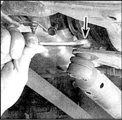
2. Loosen the nut (arrow) fasteners to the frame and remove the vibration damper.
3. Installation is carried out in the reverse order. Tighten the nuts to the specified torque.