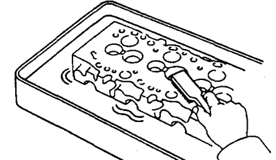
A) Turning the crankshaft, bring each piston in sequence to TDC. Using a scraper, remove carbon deposits from the bottom of each piston.
b) Remove all gasket material from the mating surface of the cylinder block.
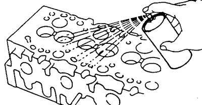
V) Use compressed air to remove gasket residue, oil, and water from the surfaces and holes in the block.
Warning: Use protective goggles during this operation.
2. Using a scraper, remove all gasket material from the contact plane of the manifold and cylinder head.
Warning: Care must be taken not to scratch the surfaces.
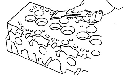
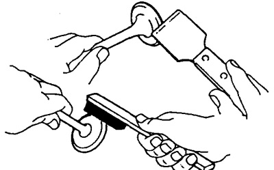
3. Using a wire brush, remove all deposits from the combustion chambers.
Warning: Care must be taken not to scratch the mating surface.
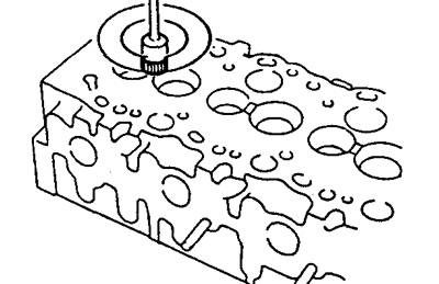
4. Using a valve guide brush and solvent, clean all valve guides.
5. Thoroughly clean the cylinder head using a soft brush and solvent.
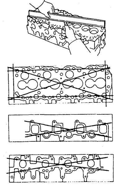
6. Check the warpage of the cylinder head welding surfaces using a precision ruler and feeler gauge.
- The maximum allowable non-flatness is 0.20 mm
7. Using a penetrating dye, check the combustion chambers, intake and exhaust ports, top and bottom surfaces of the head for cracks.
8. Clean the valves.
A) Using a scraper, scrape off the existing soot from the valve plate.
b) Using a wire brush, thoroughly clean the valve.
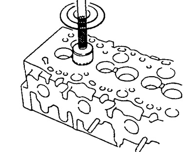
9. Check up a condition of cores of valves and directing plugs.
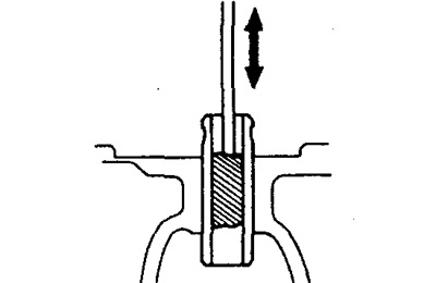
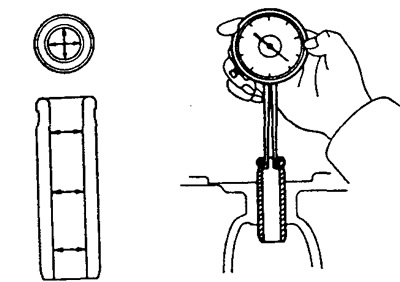
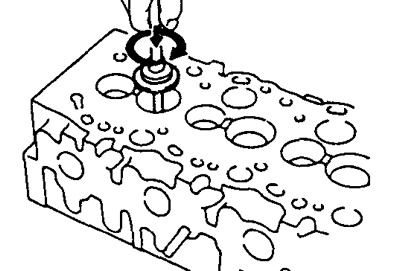
A) Using an inside gauge, measure the inside diameter of the valve guides as shown in the figure.
- Inner diameter - 8.01- 8.03 mm
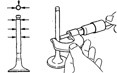
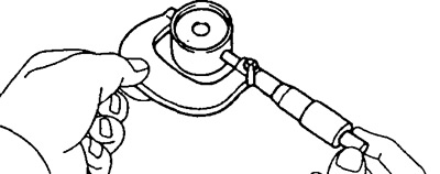
b) Using a micrometer, measure the diameter of the valve stem.
Valve stem diameter:
- Intake - 7.975-7.990 mm
- Graduation - 7.960-7.975 mm
V) Subtract the valve stem diameter from the measured valve guide bore diameter.
Rated Clearance:
- Inlet valve - 0.020-0.055mm
- Exhaust valve - 0.035- 0.070mm
Maximum allowable clearance:
- Inlet valve - 0.08mm
- Exhaust valve - 0.10mm
If the gap exceeds the maximum, replace the valves and the guide sleeve.
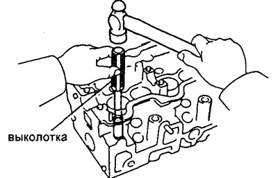
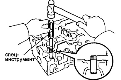
10. If necessary, replace the valve guides.
A) Using a punch and hammer, knock out the guide bushings.
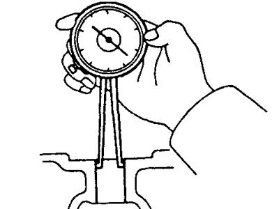
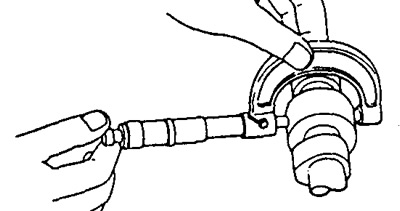
b) Measure the hole in the head of the block for the guide sleeve with an indicator-caliper.
V) Choose a new guide bushing (nominal or repair size).
If the diameter of the hole for the sleeve in the cylinder head exceeds 13.025 mm, machine the hole to the oversize.
- Repair size: 13.054-13.075 mm
If the diameter of the hole for the sleeve in the cylinder head exceeds 13.075 mm, then replace the block head.
G) Using the special tool and a hammer, lightly tap the new guide bushing into place. In this case, the sleeve should protrude from the cylinder head by 10.8 -11.2 mm.
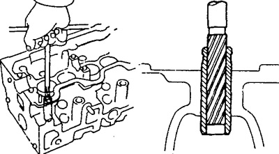
d) Sweep (08 mm), machine the inside diameter of the guide bushing to obtain the nominal clearance between the guide bushing and the valve stem.
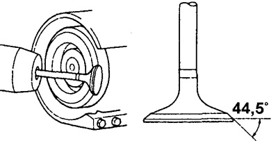
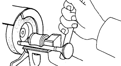
11. Checking the condition of the chamfers of the valves and their restoration.
A) Grinding should be sufficient to remove depressions and deposits.
b) Check the correct angle of the valve cone obtained as a result of grinding.
- Nominal Angle - 44.5°
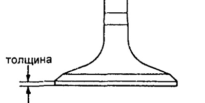
V) Check valve disc thickness.
Nominal Thickness:
- Inlet valve - 1.6 mm
- Exhaust valve - 1.7 mm
Minimum Thickness:
- Inlet valve - 1.1 mm
- Exhaust valve - 1.2 mm
If the poppet thickness is below the minimum allowable value, replace the valve.
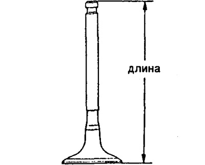
G) Check overall valve length. Valve nominal length:
- Intake - 103.29 -103.69 mm
- Graduation - 103.14 - 103.54 mm
Minimum valve length:
- Intake - 102.79 mm
- Graduation - 102.64 mm
If the valve length is shorter, replace the valve.
d) Check the valve face for wear. If there are signs of wear, grind the end or replace the valve.
Warning: Grinding must not reduce the minimum allowable overall length of the valve.
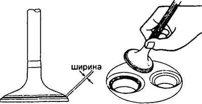
12. Check and clean valve seats.
A) Frezoy (45°) clean the saddles.
b) Check valve seat. Apply a thin layer of white to the chamfer of the valve. Press the valve against the seat. Do not turn valve.
V) Check contact between valve face and seat:
- If the imprint of paint is evenly distributed around the entire circumference of the valve face, then the axis of the valve coincides with the axis of the seat. If not, replace the valve.
- If the imprint of paint is evenly distributed around the entire circumference of the working chamfer of the valve seat, then the axis of the guide sleeve and the seat coincide. If not, mill the seat.
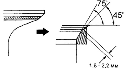
- Make sure that the contact patch is located in the middle of the valve seat and is 1.8 - 2.2 mm wide.
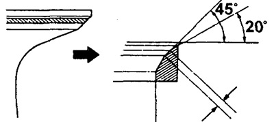
If the contact patch width is outside the specified limits, correct it as follows:
If the contact patch is too high on the valve seat, use 20°and 45°cutters to correct the seat.
If the contact patch is too low on the valve seat, use burrs (75°) And (45°).
G) Lap the valve against the valve seat with lapping paste.
d) After lapping, flush the valve and valve seat.
13. Check valve springs.
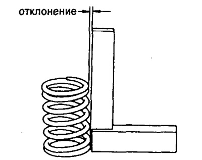
A) Using a precision square, measure the valve spring misalignment.
- Maximum deviation - 2 mm
If the deviation is more than acceptable, replace the valve spring.
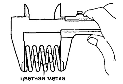
b) Using a caliper, measure the free length of the spring:
Spring length:
- With yellow mark - 46.20 mm
- With blue mark - 49.14 mm
If the spring length is not correct, replace the spring.
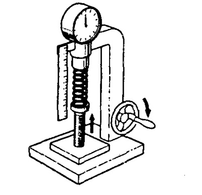
V) Using a spring tester, measure the deflection of the spring under load.
- Under load - 301 - 332 N
- Spring length - 37.0 mm
If the measurement is out of specification, replace the valve spring.
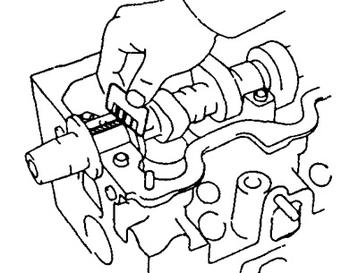
14. Check up camshafts and their bearings.
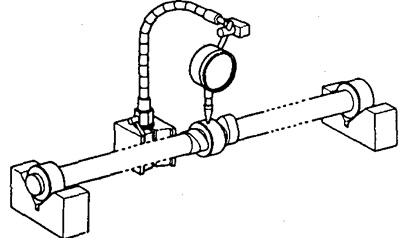
A. Check camshaft runout:
A) Install the camshaft on the prisms.
b) Use a dial indicator to measure the camshaft runout along the middle bearing journal.
- The maximum allowable runout is 0.10 mm
If the runout is greater than normal, replace the camshaft.
B. Check the height of the cams:
Nominal cam height:
inlet
- 2L - 53.45 - 53.47 mm
- 3L - 54.29 - 54.31 mm
Graduation - 54.99 - 55.01 mm
Minimum allowable cam height:
inlet
- 2L - 53.35mm
- 3L - 53.79 mm
Graduation - 54.49 mm
If the height of the cams is less than the minimum allowable value, then replace the camshaft.
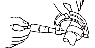
B. Check the diameter of the camshaft bearing journals using a micrometer.
Nominal size:
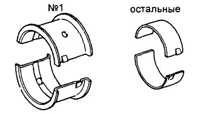
- Neck #1 - 34.969 - 34.985 mm
- The rest - 27.969 - 27.985 mm
Repair size No. 1:
- Neck #1 - 34.844 - 34.860 mm
- The rest - 27.844 - 27.860 mm
Repair size No. 2:
- Neck No. 1 - 34.719-34.735 mm
- The rest - 27.719 - 27.735 mm
If the diameter of the bearing journal is not correct, measure the clearance between the camshaft journal and the bearing.
D. Check the bearing shells for chipping and scoring. If the earbuds are damaged, replace them.
D. Check the camshaft oil clearance.
A) Clean the bearing caps and camshaft journals.
b) Lay the camshaft on the bearing surfaces of the cylinder head.
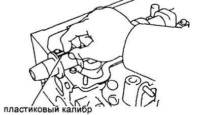
V) Place a plastic gauge on each camshaft bearing journal.
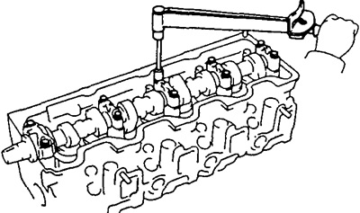
G) Install bearing caps and tighten bolts
- Tightening torque - 25 Nm
Recommendation: Do not turn the camshaft.
d) Remove bearing caps.
e) Measure the gauge width and determine the gap.
- Nominal clearance - 0.022-0.074 mm
- Maximum clearance - 0.10 mm
If the oil clearance exceeds the maximum allowable value, then replace the bearing shells. If necessary, grind or replace the camshaft.
and) Remove any remaining calibers.
E. If necessary, grind and honing the camshaft journals to oversize. Install new journal bearing shells (repair dimensions).
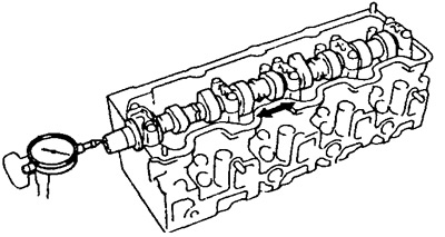
G. Check up size of an axial backlash of a camshaft.
A) Install the camshaft in place.
b) With a dial indicator, measure the axial clearance by moving the camshaft back and forth.
- Rated axial clearance - 0.080-0.280 mm
- Maximum axial clearance - 0.35 mm
If the axial clearance exceeds the maximum allowable value, then replace the bearing shell No. 1. If necessary, replace the camshaft.
15. Check up a condition of pushers of valves and apertures under pushers.
A) Measure the diameter of the pusher with a micrometer.
- Push rod diameter: 40.892 - 40.902 mm
b) Measure the diameter of the tappet hole in the cylinder head with an inside gauge indicator.
- Hole diameter: 40.960 - 40.980 mm
V) Subtract the measured tappet diameter from the measured bore diameter.
- Nominal clearance - 0.058-0.088 mm
- Maximum clearance - 0.10 mm
If the clearance exceeds the maximum value, replace the pusher. If necessary, replace the block head.
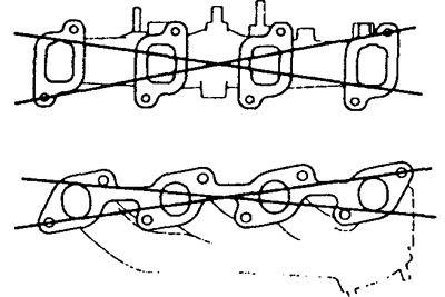
16. Check intake and exhaust manifolds. With a precision ruler and feeler gauge, measure the warping of the contact planes of the intake and exhaust manifolds.
- Maximum warping - 0.4 mm
If warpage is greater than acceptable, replace manifold.
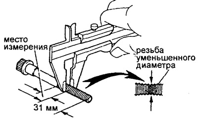
17. Check up a condition of bolts of a head of the block of cylinders.
Using a caliper, measure the outer diameter of the thread at the point of the smallest diameter.
- Nominal outer diameter - 11.80-12.00 mm
- Minimum outer diameter - 11.60 mm
If the outer diameter is less than the minimum allowable value, then replace the bolt.