
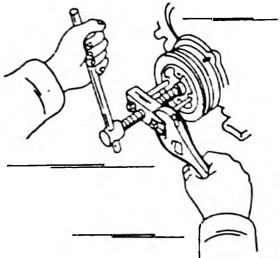
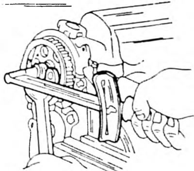
Pic. 290. Removing the crankshaft pulley using a puller.
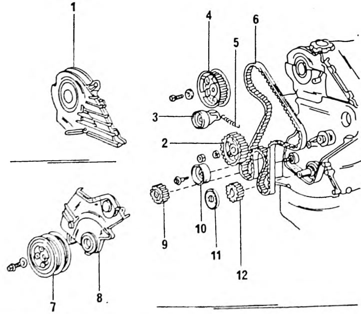
Pic. 291. Parts of the gas distribution mechanism drive on a diesel engine. 1. Toothed belt upper cover; 2. High pressure fuel pump gear; 3. Toothed belt tensioner; 4. Camshaft gear; 5. Toothed belt tensioner pull-out spring; 6. Toothed belt; 7. Crankshaft pulley; 8. Bottom timing belt cover; 9 Water pump drive gear; 10. Toothed belt guide roller; 11. Toothed belt guide roller; 12. Crankshaft gear.
- Remove the timing belts from the individual units at the front of the engine. If you have power steering, you should also remove the power steering pump pulley.
- Remove the fluid coupling and water pump pulley along with the radiator fan. To do this, unscrew the 4 coupling nuts and remove the coupling with the pulley and fan installed on it.
- Remove the crankshaft pulley bolt. To keep the crankshaft from turning, engage the gear and apply the handbrake. Unscrew the bolt with the head of the wrench. To remove a pulley, a puller is usually used, installed on the pulley in the manner indicated in Figure 290. Otherwise, you can place two pry bars under the pulley on opposite sides and use them to remove the pulley. Work is carried out under the car.
- Unscrew the top toothed belt cover from the front of the engine. To do this, remove three clamps and 5 bolts. Remove the gasket. The lower timing belt cover is removed later.
- Raise the engine using the cables or chains of the lifting device and remove the right engine mount beam.
- Remove the connections between the four glow plugs and disconnect the power cable. After this, remove the glow plugs.
- Rotate the engine crankshaft until the piston of the first cylinder is in the TDC position on the compression stroke. To turn the engine crankshaft, temporarily reinstall the crankshaft pulley. If the transmission is still on, it should be turned off. The crankshaft is rotated until the camshaft gear mark is aligned with the surface of the cylinder head, as shown in Figure 292.
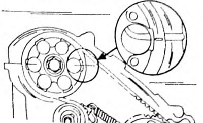
Pic. 292. When installing the piston of the first cylinder to the TDC position, the mark on the camshaft gear should coincide with the mark on the cylinder head.
- If the timing belt is to be reinstalled, mark it with a directional arrow using a felt-tip pen (the belt can be installed with the opposite side by mistake). It is best to draw an arrow directed in the direction of engine rotation. To install the toothed belt in its original position, mark the three toothed wheels and the toothed belt, as can be seen in Figure 293.
Pic. 293. Apply marks on each sprocket wheel and on the toothed belt. Place an arrow on the belt (felt-tip pen), as shown above on the camshaft gear.
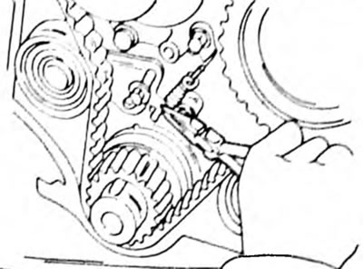
- Disconnect the return spring of the toothed belt tensioner using tweezers. Loosen the 2 bolts of the toothed belt tensioner. At the same time, press the belt to the outside so that it is free enough to remove it. Do not handle the belt with oily hands or allow it to come into contact with oil, grease or similar substances.
- If no further work is required, the toothed belt can be installed. Otherwise, follow the instructions below for removing or inspecting other parts of the timing gear drive (when, for example, the engine has high mileage).
- Unscrew the 2 bolts securing the timing belt tensioner and remove the tensioner.
- Remove the camshaft gear bolt. In this case, the gear wheel should be held. To do this, use a powerful metal rod, which is inserted into the hole of the gear and rests against the cylinder head. You can also hold the gear as shown in Figure 294.
Pic. 294. The camshaft gear can be held in the indicated way
- Remove the gear from the camshaft. The wheel sits on the shaft on a pin and therefore there is no need to mark its position on the shaft. After removing the gear, do not turn the distributor shaft.
- Hold the high pressure fuel pump drive gear in the same way and unscrew the nut. To remove the drive gear, a puller is required, shown in Figure 290. Screw the puller bolts into the two threaded holes on the gear. The oil pump drive gear is removed in the same way.
- Remove the timing belt guide roller (one bolt).
- Check for wear and integrity of all removed parts. If the tensioner sticks in some places, it should be replaced. Measure the length of the return spring. The reinstalled spring should have a length of 51.93 mm when measured between the inside of both spring hooks, as shown in Figure 295.
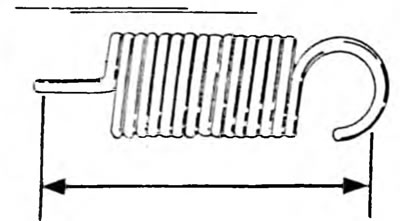
Pic. 295. The length of the return spring is measured between two arrows
Installation of the timing mechanism drive is carried out in the reverse order, and the description is given based on the fact that all parts of the timing mechanism drive were removed.
- Place the crankshaft gear on the end of the shaft, straighten the key and groove in the gear and drive the gear onto the shaft with a piece of pipe of the appropriate diameter. At the same time, watch the key so that it does not move.
- Install the oil pump drive gear in the same way, but here insert the tongue on the drive gear into the cutout on the drive shaft. Screw on the nut and tighten it to a torque of 47 Nm. In this case, the drive gear should be kept from turning.
- Install the timing belt guide roller. Tighten the bolt to 37 Nm. Check that the roller rotates easily after tightening.
- Place the high-pressure fuel pump gear onto the shaft, aligning the key with the cutout, tap the gear and screw on the nut. Hold the gear from turning, as shown in Figure 294, and tighten the nut to a torque of 65 Nm.
- Place the gear on the camshaft. The gear has a hole into which the camshaft pin must fit. Screw in the bolt with a large washer, hold the shaft as shown in Figure 294, and tighten the bolt to a torque of 100 Nm. When tightening the bolt, do not turn the shaft, as the valves may hit the piston bottoms.
- Screw in the 2 bolts securing the tensioner without fully tightening them. Tighten the middle bolt with roller to 7.5 Nm. Check that after tightening the roller rotates easily in both directions.
- Check to see if the piston of the first cylinder is in the TDC position. In this case, the mark on the crankshaft pulley should be located at the top. The mark on the camshaft gear should be aligned as shown in Figure 292, and the mark on the high pressure fuel pump drive gear should be aligned with the mark on the water pump.
- When installing a new timing belt, position it so that the letters and numbers on the rear of the engine are visible after installation.
- First, place the belt on the camshaft sprocket. Hold the high pressure fuel pump drive gear with a spanner wrench and place the belt on the gear. Check the correct engagement of the teeth of the toothed belt; in the area between the gears of the camshaft and the oil pump, the belt should be tensioned.
- Continue to hold the high pressure fuel pump gear and place the belt on the water pump gear and crankshaft sprocket. Check again that the timing belt teeth are properly engaged.
- Place the belt on the guide roller and the oil pump drive gear in this order. Check that the belt is not overtightened. All marks must match.
- When installing an old timing belt, install the belt in the manner described above, however, all the marks made with a felt-tip pen during removal must also match. The arrow must also be directed correctly. Figure 293 shows how the marks match. If the belt has moved one tooth, it must be re-routed.
- Connect the return spring to the tensioner in the manner shown in Figure 296. After connecting the spring, loosen the 2 bolts of the tensioner. In this case, the tension roller is pulled inward and tensions the toothed belt.
Pic. 296. Connecting the return spring of the toothed belt tension roller
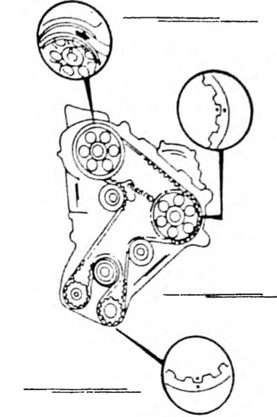
- Tighten the bolt at the front end of the crankshaft until the crankshaft begins to turn. Turn the crankshaft exactly two turns and check that all marks are aligned as shown in Figure 297. If necessary, remove and reinstall the belt.
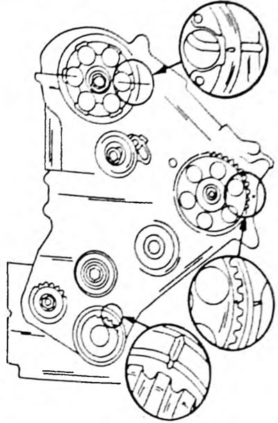
Pic. 297. The circles show the position of the marks of various drive gears
- Tighten the tension roller bolts to 37 Nm without moving the mounting plate.
- Install the right engine mount support bracket. Tighten the smaller bolts to a torque of 37 Nm, the larger bolts to 65 Nm.
- If power steering is installed, do not fully tighten the large bolts yet.
- Screw in the four glow plugs and tighten them to 13 Nm. Connect the current connectors to the spark plugs, install the current busbar with insulating washers, washers and nuts and put on four rubber tips.
- Place the toothed belt guide washer onto the end of the crankshaft. At the same time, align the wedge guide along the key. The bent edge of the guide washer should face outward, as shown in Figure 298. Place the lower toothed belt cover with the gasket and tighten the 5 bolts evenly.
- Install the crankshaft pulley (pay attention to the key and cutout). A piece of pipe is used for mounting. Screw in and tighten the bolt to 100 Nm. In this case, the gear must be engaged to keep the shaft from turning.
- Install the top timing belt cover with a new gasket and secure with 5 bolts and 3 clamps.
- Secure the power steering pump with 3 bolts. Tighten the bolts to 40 Nm. Install the pump pulley temporarily now.
- Install the power steering pump and alternator drive belt and adjust the belt tension as described in the appropriate chapter for the alternator (chapter "Cooling system") and for power steering pump (chapter "Steering"). The temporarily installed power steering pump pulley can now be tightened. To do this, press the belt with your thumb and use the socket and torque wrench to tighten the nuts until the tightening torque is 45 Nm.