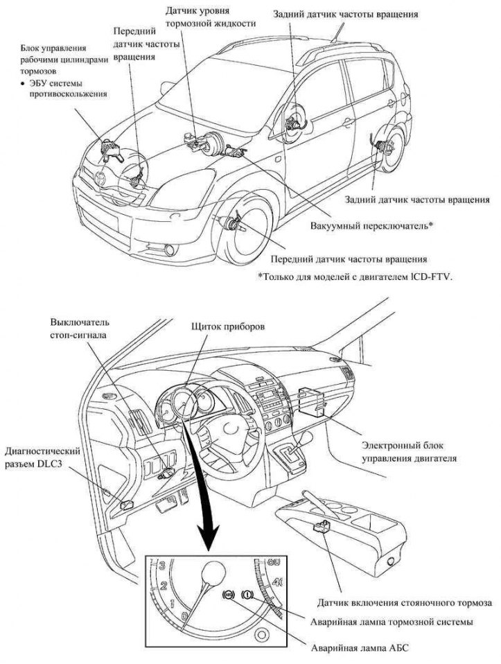
Pic. 6.3. Location of the main components of the brake force distribution system (EBD)
The mechanical brake force distribution system used on previous models has given way to an electronic control unit (ECU) anti-skid system, which with high precision controls the braking force depending on the driving conditions of the car.
Distribution of brake force between front and rear wheels
When you press the brake pedal while driving in a straight line, the load on the rear wheels is reduced, and the load on the front wheels is increased. The ABS electronic control unit recognizes this condition from the signals from the speed sensors and sends a command to the brake actuator control unit, adjusting the braking force transmitted to the rear wheels.
The magnitude of this force depends, for example, on the load of the vehicle, as well as on the rate of deceleration. This ensures optimal distribution of the braking forces transmitted to the rear wheels, depending on the driving conditions.
Distribution of braking force between right and left wheels (when braking in a turn)
When braking in a turn, the load on the inner wheels decreases, and on the outer wheels it increases. The anti-skid electronic control unit recognizes this condition from the signals from the speed sensors and sends a command to the brake actuator control unit, ensuring optimal distribution of the braking force between the inner and outer wheels.
Brake cylinder control unit
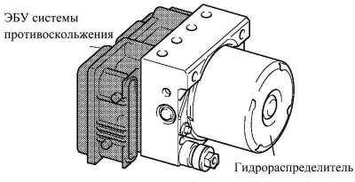
Pic. 6.4. Brake cylinder control unit
The brake cylinder control unit consists of a hydraulic distributor and an anti-skid control unit.
The control unit for the working cylinders of the brakes manufactured by BOSCH is used, as on Avensis cars.
System operation
The ABS electronic control unit calculates the speed and deceleration of each wheel, and controls the wheel lock based on signals from 4 speed sensors. Depending on whether the wheels slip, the electronic control unit of the anti-skid system regulates the pressure of the brake fluid in the working cylinder of each wheel, including the check and pressure reducing valves in one of three modes: reducing, holding and increasing pressure.
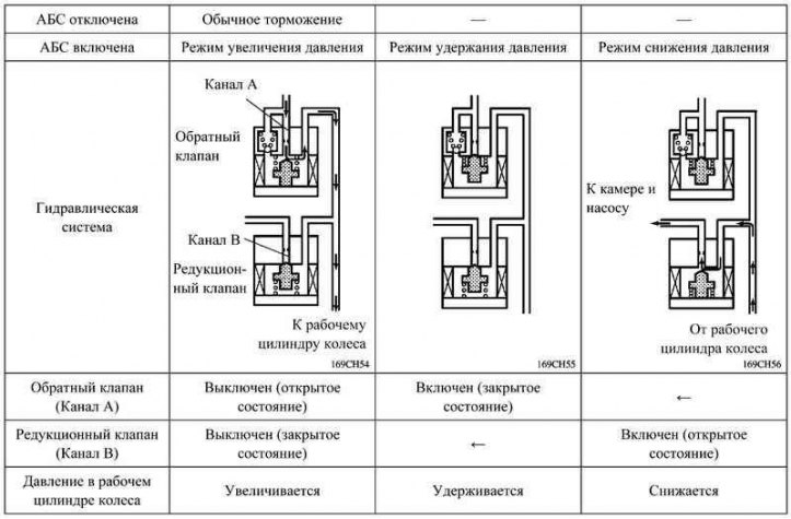
Pic. 6.5. How the system works (EBD)
Diagnostics
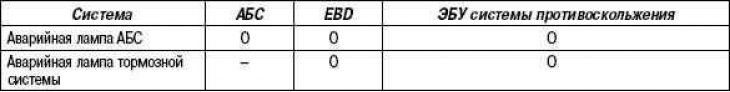
When the skid control ECU detects an ABS malfunction with electronic brake force distribution (EBD) the ABS warning light and the brake system warning light come on, indicating a system malfunction (see table below).
At the same time, electronic fault codes are stored (DTC). DTC can be read by the number of flashes of the ABS warning lamp: to do this, connect the SST diagnostic tool to the Tc and CG contacts of the DLC3 diagnostic connector (09843-18040) or microprocessor tester II.
The diagnostic system provides an active mode for diagnosing sensor signals. The function is activated by connecting to terminals Ts and CG of the diagnostic connector DLC3 of the diagnostic tool SST (09843-18040) or microprocessor tester II.
When faults are detected during the sensor check process, the skid control ECU stores the corresponding electronic DTCs. DTCs stored during the sensor test can be read by the number of blinks of the ABS warning lamp when the Tc and CG contacts of the DLC3 diagnostic connector are closed or using the microprocessor tester II.
Emergency operation
In the event of a malfunction in the ABS system, the skid control ECU blocks the activation of the anti-lock braking system.
If a malfunction occurs in the electronic brake force distribution system (EBD) The skid control ECU is blocking the skid control. In this case, the brake system will work as if there was no ABS with electronic brake force distribution (EBD).