
Removing
Typical AT installation diagram
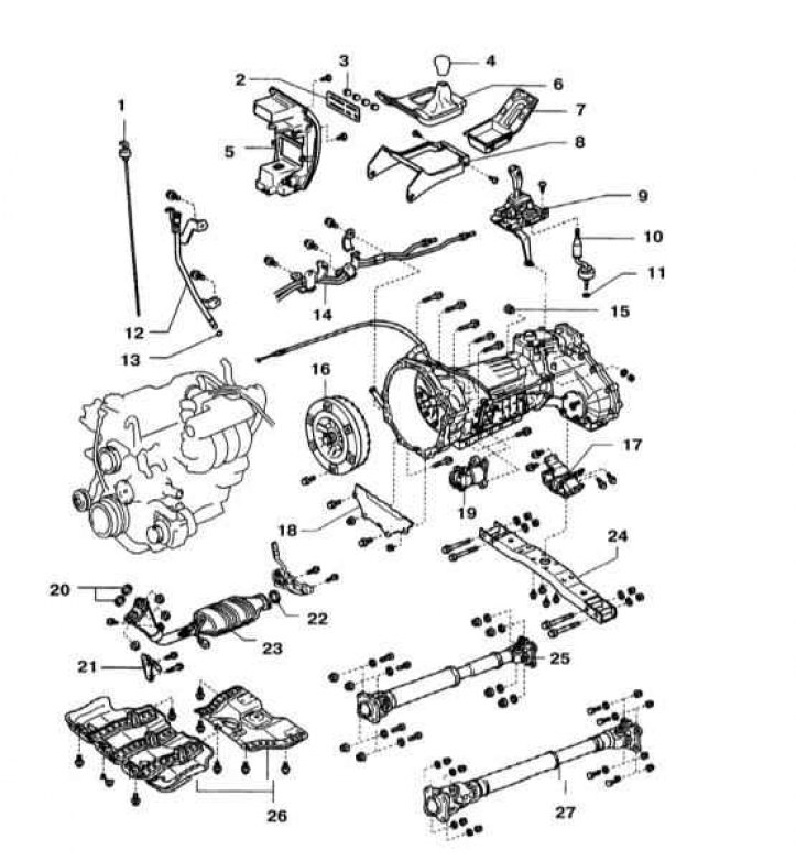
1 - ATF level probe; 2 - Heater control panel; 3 - Heater control handles; 4 - The handle of the lever for switching modes of the transfer case; 5 - Central section of the instrument panel trim; 6 - Top panel of the front console; 7 - Top panel of the rear console; 8 - Assembling the front console; 9 - Assembling the gear selector lever; 10 - Lever for switching modes of the transfer case; 11 - Retaining ring; 12 - Filler tube; 13 - O-ring; 14 - Oil cooler tube; 15 - Plug for hydraulic check; 16 - Rotation converter; 17 - Rear suspension support of the power unit; 18 - Rear end plate; 19 - Starter; 20 - Sealing gaskets; 21 - Support bracket; 22 - Sealing gasket; 23 - Receiving section of the exhaust system; 24 - Cross beam; 25 - Front propeller shaft; 26 - Crankcase protection; 27 - Rear driveshaft
1. Disconnect from the battery at first a negative wire, then positive.
Attention! If the stereo system installed in the car is equipped with a security code, before disconnecting the battery, make sure that you have the correct combination to activate the audio system!
Remove the battery from the tray (see chapter Engine electrical equipment).
2. Remove the air filter assembly, fan drive belt, diffuser and expansion tank.
3. Remove the AT selector lever assembly (see Section Removal and installation of assembly of the lever of the selector AT).
4. Jack up the car and put it on stands.
5. If equipped, remove the crankcase protection.
6. Disconnect from collectors reception pipes of system of release of the fulfilled gases.
7. Place a container under the back of the AT to collect the liquid. Mark and remove front and rear driveshafts (see chapter transmission line).
8. Remove the ATF dipstick assembly (refer to illustration above).
9. Disconnect drafts of a drive AT and a distributing box.
10. Disconnect the following connectors:
- VSS sensors #1 and #2;
- Speed sensor 0/D;
- solenoid valve;
- ATF temperature sensor;
- P/N sensor (launch permissions);
- Center differential lock sensor;
- Electric motor of the executive device;
- Sensor L4
- Transfer box neutral position sensor
11. Remove a cover of a bell and give six bolts of fastening of the hydrotransformer to a driving disk.
12. Disconnect from АТ tubes of an oil cooler.
13. Supporting the AT with a jack and laying a piece of board between them, remove the transverse beam.
14. So that the torque converter does not fall out of the AT, do not tilt it forward.
Installation
1. If filmed, establish the hydrotransformer in АТ. Turning it little by little, carefully push the torque converter into the box until it stops. With the correct fit of the transformer, the distance from its end to the cut of the bell must be at least 17.1 mm.
2. Establish АТ on directing plugs of the engine. Wrap the mounting bolts and tighten them with a force of 72 Nm.
3. Establish a cross beam and tighten bolts of its fastening the moment of 50 Nm. Tighten the nuts with a force of 74 Nm.
4. Connect the oil cooler tubes to the AT by tightening the hex fittings to 32 Nm.
5. Wrap six bolts of fastening of the hydrotransformer to a driving disk. Install the green bolt first, then the rest. Rotate the crankshaft for sequential access to the bolts. Tighten the bolts to 48 Nm.
6. Further installation is carried out in the reverse order to the dismantling of the components.
7. Fill the transmission with ATF (see chapter Vehicle settings and routine maintenance), start the engine and inspect the unit for signs of leaks.