
Throttle Position Sensor Test Table (1988-92)
Clearance between lever and throttle screw | Pin Pairs | Resistance |
0 mm | VTA-E2 | 0.3 - 6.3 kOhm |
0.50 mm | IDL-V2 | < 2.3 kΩ |
0.75 mm | IDL-V2 | infinity |
damper fully open | VTA-E2 | 3.5 - 10.3 kOhm |
– | VC-E2 | 4.52 - 8.25 kOhm |
Throttle Position Sensor Test Table (since 1983)
Clearance between lever and throttle screw | Pin Pairs | Resistance |
0 mm | VTA-E2 | 0.2 - 5.7 kOhm |
0.50 mm | IDL-V2 | < 2.3 kΩ |
0.75 mm | IDL-V2 | infinity |
damper fully open | VTA-E2 | 2.0 - 10.2 kOhm |
– | VC-E2 | 2.5 - 5.9 kOhm |
Examination
1. Disconnect the connector from the sensor.
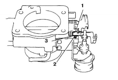
2. Between the throttle stop screw and the lever, lay a feeler gauge of the specified thickness (1 - lever, 2 - limiter, 3 - place for laying the probe).
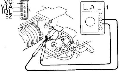 | 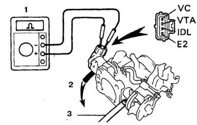 |
3. Measure the resistance between the pairs of leads indicated in the respective tables, laying probes of various thicknesses (1 - ohmmeter, 2 - vacuum, 3 - probe).
4. If the measured resistance differs from that indicated in the table, then between the lever and the damper screw, lay a probe 0.93 mm thick (on cars 1988-92.) or 0.62 mm (on cars since 1993) and connect an ohmmeter to the IDL and E2 terminals. Loosen the sensor mounting screws and slowly turn the sensor clockwise until the ohmmeter shows an open.
5. Tighten the screws and, using feeler gauges of the specified thickness, again check the resistance between the indicated terminals.
6. If the adjustment fails to achieve the specified resistances, then remove the sensor and replace, then adjust.