
Details of the fuel pump power circuit (1988-90)
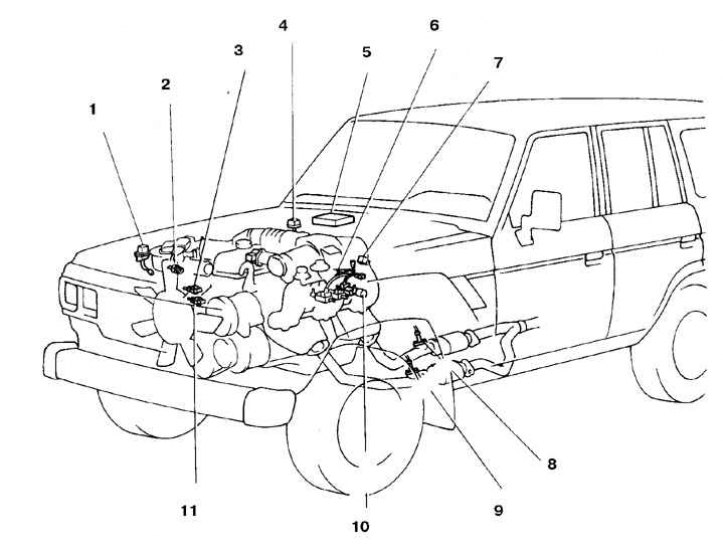
1. The main relay of the injection system; 2. Contact fluid temperature sensor; 3. Starting nozzle; 4. Diagnostic connector; 5. Processor unit; 7. Fuel pump relay; 8, 9. Oxygen sensor; 10. Vacuum valve; 11. Fluid temperature sensor
Details of the fuel pump power circuit (1991-92)
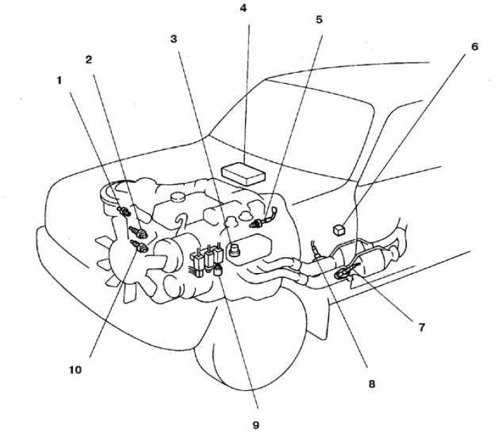
1. Contact fluid temperature sensor; 2. Starting nozzle; 3. The main relay of the injection system; 4. Processor unit; 6. Fuel pump relay; 7, 8. Oxygen sensor; 9. Vacuum valve (controlled by the processor unit); 10. Fluid temperature sensor
The layout of the parts of the fuel pump power circuit (since 1993)
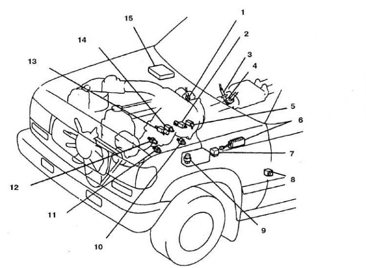
1. Gas temperature sensor of the recirculation system; 2. Vacuum valve (for pulsed air system); 3, 4. Heated oxygen sensor 1 and 2; 5. Vacuum valve of the recirculation system; 6. Resistor; 7. The relay of inclusion of the fuel pump; 8. Fuel pump circuit relay; 9. The main relay of the injection system; 10, 11. Knock sensor; 12. Temperature sensor; 13. Vacuum valve (controlled by the processor unit); 14. Vacuum valve of the gasoline vapor recovery system; 15. Processing unit
Examination
Fuel pump
1. Turn on the ignition (do not start the engine).
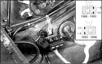
2. Connect the jumper pins B+ and FP on the diagnostic connector.
Attention! On all cars 1988-1994. diagnostic connector is different. Refer to the connector wiring shown on the label affixed under the connector.
3. On cars manufactured in 1995, power supply to the fuel pump through the diagnostic connector is not provided. On these vehicles, the engine must be started to read the fuel pressure.
4. After jumpering the indicated conclusions, voltage is applied to the fuel pump. In the place under the rear seat, the operation of the pump should be heard, and fuel pressure should be felt on the hose from the fuel filter.
5. Disconnect the jumper. Install the plug on the diagnostic connector.
6. Switch off the ignition.
7. If the pump does not work, then check the fuse of the main injection system relay (EFI relay) at 15 A.
8. Check 30A ignition key fuse (insert AM2, seesubsection 11.3).
9. Check injection system main relay (EFI relay) and fuel pump relay.
10. Check for voltage at the fuel pump.
11. Check wiring and connectors.
12. Cars after 1993 are additionally equipped with a fuel pump switch-on relay, on which the voltage must also be checked.
Fuel pressure
1. To perform the procedure described below, you will need a manometer for a pressure of at least 3 kgf / cm2. The hose end must be of type "banjo", i.e. sealed with a bolt with an internal through channel
2. In the absence of a special pressure gauge, get a ready-made fitting of the type "banjo", with an internal diameter of 12 mm, to which a hose with a clamp from your pressure gauge fits.
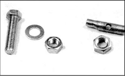
3. In the absence of a ready-made fitting, it can be made from a bolt with a M12x1.25 mm thread. Grind off the head of the bolt and drill two holes - one through the center of the bolt, and the other through the center across the bolt, intersecting with the longitudinal hole. Screw on the nut and locknut, sealing the threads with Teflon tape.
4. Unscrew the filler cap of the tank.
5. Make sure the battery voltage is at least 12V.
6. Decompress the fuel system.
7. If there is an adapter on the pressure gauge, unscrew the bolt on the distributor and screw in the adapter.
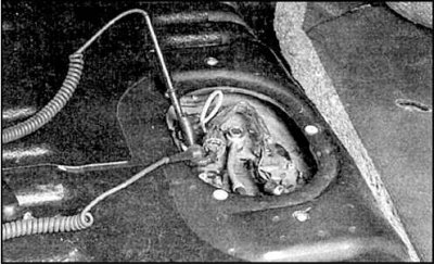
8. Screw in the adapter, made by yourself, as shown in the photo.
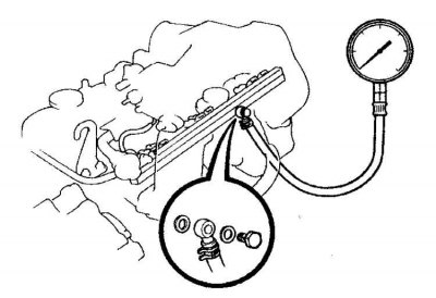
9. Connect the manometer in the following order:
- in the presence of "full-time" pressure gauge, connect it to a special adapter installed on the fuel distributor;
- be sure to install new gaskets on both sides of the adapter;
- screw the self-made adapter into the fuel filter, tighten the lock nut;
- connect the pressure gauge hose and secure with a clamp.
10. Wipe up spilled gasoline from the fuel dispenser or filter.
11. Place the automatic transmission selector lever in the Park position, or the gearshift lever in the neutral position.
12. On all cars 1988-1994. short-circuit conclusions B+ and FP on the diagnostic connector using a special jumper.
Attention! On vehicles manufactured in 1995, power supply to the fuel pump through the diagnostic socket is not provided. On these vehicles, the engine must be started to read the fuel pressure.
13. Turn on the ignition (do not start the engine). Read the pressure reading and compare it with the standard.
14. If the pressure is high, check the fuel return line. If gasoline flows through the fuel line, replace the fuel pressure regulator.
15. If the pressure is low, then pinch the fuel return line. If the pressure rises, replace the fuel pressure regulator. If the pressure does not increase, then check the fuel supply line, fuel pump and fuel filter.
16. Remove the jumper from the diagnostic connector, or from the fuel pump connector.
17. Start the engine.
18. Check the fuel pressure at idle, compare the result with the standard.
19. If the pressure is out of specification, check the vacuum hose and fuel pressure regulator.
20. Stop the engine and check that the fuel pressure is maintained at 1.3 kgf/cm2 within 5 minutes after stopping. If the pressure drops faster, then the cause may be a leak in the fuel pump, pressure regulator, or injector.