
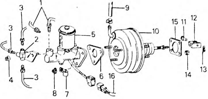
Pic. 263. Fastening of the main brake cylinder and hydraulic booster of the brake system. 1. Union nuts, 15 Nm; 2. Throne; 3. Union nuts, 15 Nm; 4. Nut. 13 Nm; 5. Master brake cylinder; 6. The gasket is always replaced; 7. Clamp clamp; 8. Nut, 13 Nm; 9. Vacuum hose; 10. Power steering; 11. Cotter pin; 12. Fork head; 13. Bracket; 14. Nut. 13 Nm; 15. Gasket, always replaced; 16. Connector, liquid level.
If a new hydraulic booster is installed, the length of the push rod of the device must be adjusted. This requires a special tool (09737-00010), shown in Figure 264. Place the template on the upper side of the master cylinder and turn the adjusting bolt in the middle of the template until it touches the piston of the master cylinder. Without moving the template bolt, place the template on the surface of the hydraulic booster and use a feeler gauge to measure the gap between the pusher rod and the template adjusting bolt. If the gap goes beyond 0-0.4 mm, loosen the locknuts of the pusher rod adjuster and rearrange the rod so that the required clearance is ensured. After adjustment, tighten the locknut.
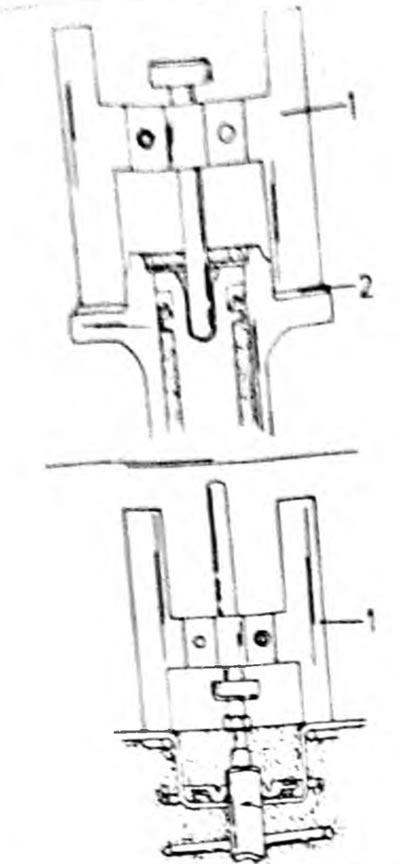
Pic. 264.