
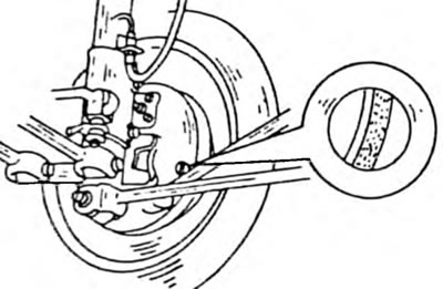
Pic. 248. The thickness of the brake pads can be controlled through the inspection hole on the rear side of the brake
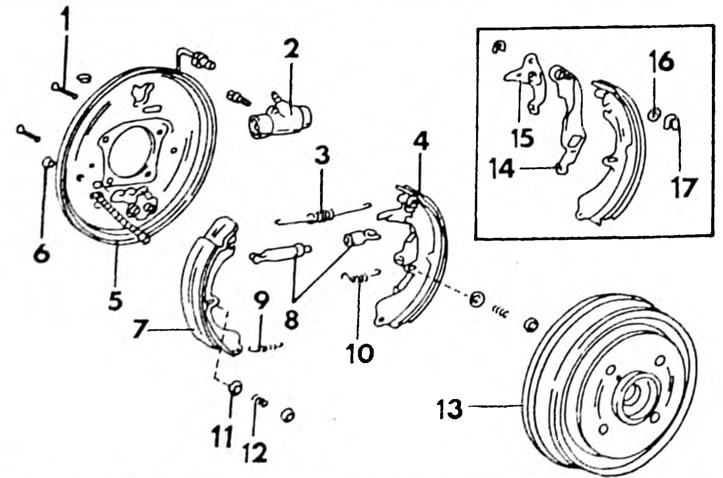
Pic. 249. Installation drawing of the rear wheel brake. The details of the installation mechanism are shown separately. 1. Brake shield pin holding the brake pad; 2. Wheel brake cylinder; 3. Upper return spring; 4. Rear brake pad; 5. Brake shield; 6. Plug; 7. Front brake pad; 8. Spacer bar; 9. Lower return spring; 10. Adjustment lever spring; 11. Spring cup; 12. Spring; 13. Brake drum; 14. Handbrake actuator lever; 15. Installation lever; 16.Adjusting washer; 17. Lock washer.
- Place the rear of the car on stands.
- Block the front wheels accordingly (substitute bricks), so that the car cannot move off the stands.
- Remove the rear wheels.
- Release the handbrake.
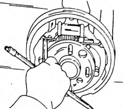
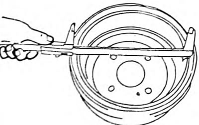
- Remove the brake drum. Sometimes it can be difficult to tighten the brake drum. In this case, insert a screwdriver into the slot on the back of the brake shield and move the adjusting gear back. Since the gear wheel is also held by the setting lever, you need to insert a second screwdriver to press the lever. This work is shown in Figure 250.

Pic. 250. Releasing the installation mechanism if the brake drum is not removed.
- On each brake pad, use pliers to grasp the head of the retaining pin and rotate it 90°until it disengages from the spring cup pin.
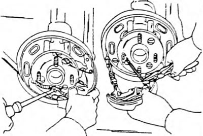
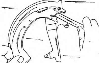
- Using pliers or as shown in Figure 251, disconnect the upper return spring.
Pic. 251. The upper coin return spring must be removed in the manner indicated.
- Remove the lower parts of the brake pads from the lower support and remove the brake pads from the brake shield. The handbrake spacer remains temporarily on the shoe. If the brake pads are to be reinstalled, mark the installation side on them.
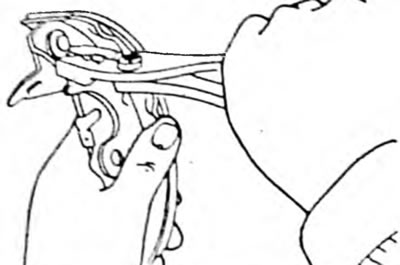
- Grasp the handbrake cable, as shown in Figure 252, press the lever against the spring and disconnect the handbrake cable.
Pic. 252. Disconnecting the handbrake cable.
- Both levers remain on the block.
If scratches are found on the surface of the brake drum, the drum can be bored, provided that the specified maximum permissible diameter is maintained. It is 201.0 mm. Also measure the ovality of the brake drums, especially if the drums have been overheated during operation. At no point should the deviation from the diameter exceed 0.10 mm. If the thickness of the brake pad lining material is less than 1.0 mm, the pads must be replaced as a set. Deformed springs, if they were bent during removal, must be replaced. Unscrew the installation mechanisms and lubricate the threads with heat-resistant grease. Screw the threaded pusher in and out several times to make sure it can be adjusted freely. Please note that one pusher has a left-hand thread, and the other has a right-hand thread. Be sure to note which wheel this pusher belongs to. If the brake pads are being replaced, both levers are swapped from the old brake pads. To do this, remove the U-shaped bracket and remove the lever.
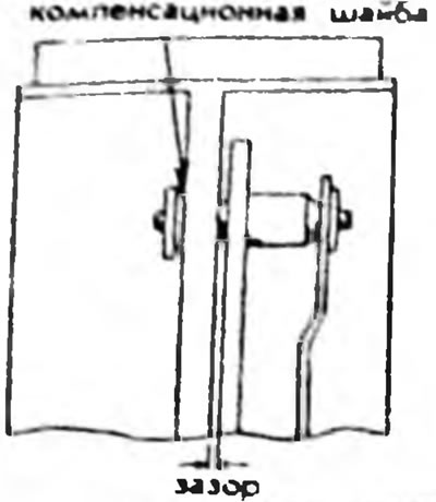
If the levers are installed on new brake pads, they need to be adjusted. To do this, place both levers on the brake shoe and temporarily secure them with an old spring clip. As shown in Figure 253, measure the gap between the brake pad and the first lever with a feeler gauge. The gap should be from 0 to 0.35 mm and can be adjusted by installing a compensation washer.
Pic. 253. Measuring the gap between the handbrake lever and the brake pad using a feeler gauge. The gap can be adjusted by installing a compensation washer.
Expansion washers available in six different sizes (0.2, 0.3, 0.4 0.5, 0.6 and 0.9 mm). Install the appropriate washer and new spring clip (Pic. 254) and compress the bracket with pliers, as shown in Figure 255. Check that the spring bracket is seated on the other side of the pin and that the lever moves freely. The description of the wheel brake cylinder is given in Chapter 15.3.2. Installation of brake pads is carried out in reverse order, taking into account the following points:
Pic. 254. Brake pad size and position of the mounting washer, indicating the location of the gap measurement
Pic. 255. Removing the mounting bracket after installing the brake pad lever
- In areas of contact with the brake pads, lubricate the brake disc with heat-resistant grease. Lubricate the pin at the end of the adjusting gear with the same grease.
- Connect the handbrake cable and spring to the adjustment lever.
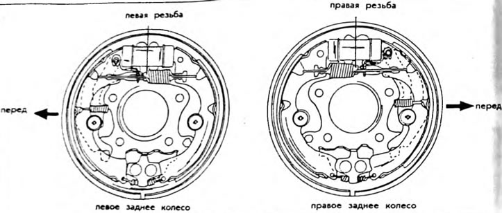
- Install the brake pads, insert the lower return spring and use a screwdriver to position the brake pads in the correct position. The spacer bar must be between the pads. The spacer bars cannot be moved to the opposite side. Figure 254 shows the correct installation depending on the thread direction. The figure shows the design for the sedan, coupe and combi.
- Connect the end of the upper spring to the brake pad and stretch the spring with a wire hook so that you can insert the other end into the hole in the shield with a screwdriver.
Pic. 256. Method of installing a spacer bar between brake pads
- Before installing the brake drum, measure the exact diameter of the drum, as shown in Figure 257, and then place a caliper, without moving it, on the well-aligned brake pads.
Pic. 257. Measuring the diameter of the brake drum. Take measurements in several places
- Move the setting mechanism apart so that a 0.6 mm feeler gauge can be inserted between the caliper and the brake pad. In this way, the initial installation of the installation mechanism is carried out.