



- Raise the front of the vehicle and place it on stands.
- Remove the front wheels and temporarily secure the brake discs with two wheel nuts.
- Remove the two bolts shown in Figure 237 and remove the brake caliper. Leave the caliper on the hose, but secure it to a piece of wire so that it does not sag.
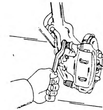
Fig. 237. Removing and installing the brake caliper cylinder
- Now the brake pads are lying freely. There is a metal lining on the outside. Pull out the parts one by one and immediately mark the sides from which they are removed, as you may have to install the same pads again. Figure 238 shows the removed parts. It should be noted that the washer (8) is installed only on cars with 14-inch wheels. The shape of the washers on cars with 13-inch wheels is different.
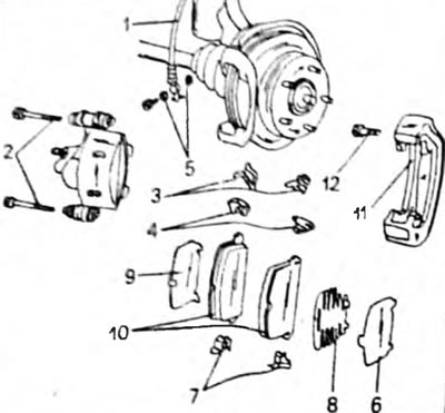
Fig. 238. Removing and installing brake pads. 1. Brake hose; 2. Bolt 25 Nm; 3. Brake shoe support brackets; 4. Brake pad wear indicator brackets; 5. Compaction; 6. Overlay; 7. Brake shoe support brackets; 8. Overlay, 3S engine - FE; 9. Overlay; 10. Brake shoe; 11. Mounting frame; 12. Mounting frame bolts, 90 Nm
- Brake pads must be replaced as a set and, to equalize wear, never switch brake pads from one side to the other.
- Clean the removed brake caliper parts and check for any traces of rust on the working surfaces of the brake pads (if necessary, brush with a wire brush). Check the thickness of the remaining material. For this purpose, you can use a depth gauge or a measuring ruler, as shown in Figure 239. If one of the brake pads soon reaches a thickness of 1.0 mm, all brake pads in the set must be replaced. This is done even when some pads are still in good condition.
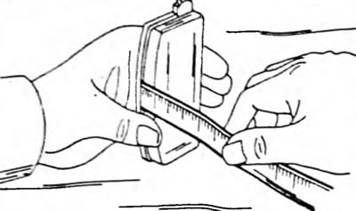
Fig. 239. Measuring the thickness of the brake pad with a measuring ruler
- Install the parts shown in Figure 238 in the caliper mounting frame. First, install the 4 brake shoe guide plates in the locations shown in Figure 240. The wear indicator must be replaced. It has an arrow that must point in the direction of rotation of the brake disc. Figure 241 shows the correct position of the wear indicator. The spacer washers must also be replaced.
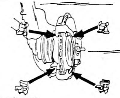
Fig.240. Insert 4 brake shoe support plates into the indicated locations.
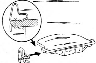
Fig. 241. Correct installation of the brake pad wear sensor.
- Installation is carried out in reverse order using Figure 238.
- Insert the brake shoe into the guides, ensuring that the spacer washers are seated correctly.
- Open the air bleed valve and simultaneously press the piston into the cylinder hole with the hammer handle. Do not use metal objects. If you succeed in doing this, you will not have to bleed the brake system. Otherwise, you should suck out the brake fluid from the reservoir, since the fluid will flow out of the overfilled reservoir during this work.
- Position the brake caliper cylinder without damaging the rubber seals so that the bolts can be inserted.
- Tighten the bolts to 25 Nm.
- After lowering the car, press the brake pedal several times to bring the brake pads to the brake discs. Remember that new brake pads need to be worked in and do not provide full braking efficiency at first.