
- Replace all rubber cuffs. Repair kits are available and all parts of the repair kit must be used during assembly.
- Disassembly and assembly must be carried out in clean conditions.
- Before installation, place all rubber seals in clean brake fluid for a while.
- When ordering a repair kit, please indicate the chassis number and model, as the wheel brake cylinders have been modified.
Using Figure 260:
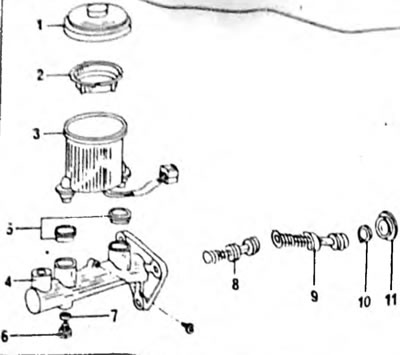
Pic. 260. Installation drawing of the main brake cylinder. The shape of the tank is not the same on all models. 1. Tank cover; 2. Filter mesh; 3. Tank; 4. Cylinder body; 5. Rubber tips; 6. Bolt, 10 Nm; 7. The oil seal is always replaced; 8. Intermediate piston and spring; 9. Working piston and spring; 10. Retaining ring; 11. Rubber cuff
- Remove cover (1) and filter (2) and drain the liquid.
- Clamp the cylinder in a vice.
- Remove the dust cap (11).
- Using a circlip pliers, remove the circlip from the hole (10). To do this, push the pistons a little inward to remove the spring force from the ring, that is, bring both handles of the pliers together, as shown in Figure 261.
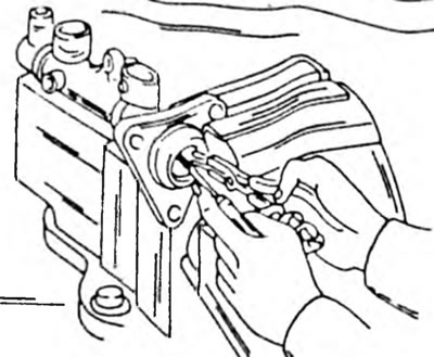
Pic. 261. Removing the retaining ring from the hole when retracting the piston.
- Unscrew the thrust bolt from the bottom when pushing the piston into the cylinder, as shown in Figure 262. Do not lose the sealing washer.

Pic. 262. When turning out or screwing in the thrust screw, press the piston into the hole.
- Pull all internal parts out of the hole. If the parts are firmly seated, they can be blown out with compressed air. To do this, connect the compressed air hose to one of the holes in the cylinder and close the other hole in the tube with your finger. Wrap the cylinder with a rag to prevent the parts from scattering.
- Remove the seals from the pistons with your fingers.
- If further disassembly is required, remove the two small bolts and pull the reservoir out of the rubber tips. The rubber tips can be pressed out with a screwdriver. Wash all parts in brake fluid or alcohol. If the cylinder bore or piston still looks good, measure the bore diameter and the outer diameter of the piston with a micrometer. The difference between both dimensions, i.e. play, should not exceed 0.15 mm. Immerse new piston cups in brake fluid and place them on the pistons. Assemble the cylinder in accordance with the installation drawing. Using a screwdriver, insert the piston into the hole and screw in the stop bolt (6), without putting in much effort (pic. 262). After this, release the screwdriver and check whether the piston is held. Insert the retaining ring at the end of the cylinder bore. At the same time, press the piston into the hole, as shown in Figure 261, and insert the ring using circlip pliers. Check that the locking ring (10) fits well into the groove. When installing the tank, it should be turned so that the mark "Max" was visible from the front. Tighten the bolt while pressing the reservoir down.