



Contents: General information ↓ Checking and adjusting wheel…↓ Checking and adjusting the camber…↓ Checking and adjusting the front…↓
General information
Wheel alignment angles of a car
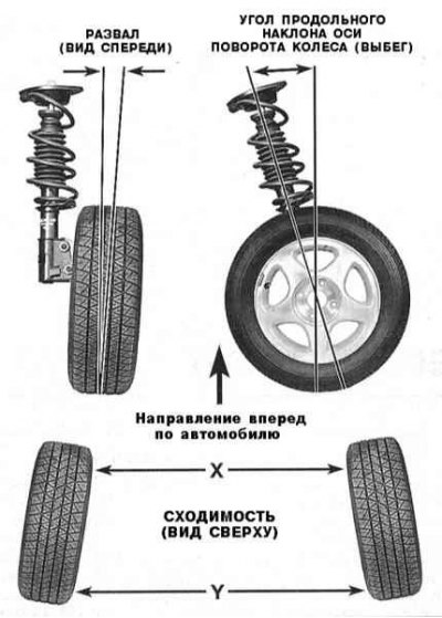
A – B = C (Wheel camber angle in degrees)
D = Caster angle (run-out) in degrees
E – F = Convergence in millimeters
G = Convergence in degrees
1. Front wheel alignment angles determine the geometry of the latter's position relative to the vehicle's suspension and the road surface. Violation of this geometry adjustment leads to decreased vehicle controllability and increased tire wear. The front wheel alignment angles subject to control include camber, runout (longitudinal tilt angle of the wheel pivot axis) and convergence (refer to the illustration above).
2. Adjusting the geometry of the front suspension requires the use of special expensive and bulky equipment and its implementation should be entrusted to car service specialists.
3. Toe-in is the amount of convergence of the front edges of the car wheels. This violation of the parallelism of the wheel installation helps to minimize tread wear due to skidding when turning. With zero toe-in, the distance between the front edges of the wheels is equal to the distance between their rear edges. Normal toe-in usually does not exceed fractions of an inch (1 inch = 2.54 cm). Adjustment of the toe-in of the front wheels is carried out by adjusting the length of the steering rods by changing the position of their tips. Violation of the toe-in adjustment leads to accelerated wear of the tire treads due to their slippage on the road surface.
4. Camber is the angle of the plane of the wheels relative to the vertical. If the wheels are tilted with their upper edges outward, the camber is called positive, and vice versa. The camber value is measured in degrees. Correct camber adjustment determines the size and position of the contact patch of the treads with the road and allows for compensation of changes in the suspension geometry when turning and when the car is moving on an uneven road surface. Camber adjustment is made by rotating special adjustment cams installed in the front and rear parts of the upper suspension arms.
5. The run-out is the longitudinal inclination angle of the wheel turning axis, i.e., the angle of deviation from the vertical of the wheel turning axis in the plane of the latter. If the turning axis is tilted backwards, the run-out is called positive, and vice versa. The run-out is adjusted simultaneously with the camber adjustment. By analogy, the transverse angle of the wheel turning axis is the angle of deviation of the imaginary kingpin from the vertical in the plane perpendicular to the vehicle's DP.
Checking and adjusting wheel alignment angles
1. Assess the degree of wear of the treads, check the tire inflation pressure.
2. Make sure that the lateral runout of the wheels does not exceed 1.2 mm.
3. Check the front wheel bearing preload adjustment.
4. Assess the reliability of fastening of the front suspension components and steering gear. Assess the amount of play in the ball joints.
5. Check the condition of the shock absorbers.
Checking and adjusting the camber and longitudinal and transverse tilt angles of the wheel pivot axis
1. Drive the car onto the adjustment stand and measure the controlled parameters listed in the subsection heading (see Specifications).
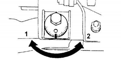
2a. If the camber and/or caster angle of the wheel axis (run-out) does not comply with the accepted standards, the appropriate adjustment should be made by rotating the front...
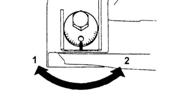
2b....and/or the rear adjusting cam of the lower suspension arm (refer to accompanying illustrations).
3. If, after adjusting the camber and run-out, the lateral tilt angle of the wheel pivot axis is outside the permissible range, the condition of the steering knuckle and front suspension components should be checked.
Checking and adjusting the front wheel alignment
1. Rock the car to settle the suspension components.
2. Set the front wheels in a straight-ahead position and roll the vehicle forward approximately 5 meters.
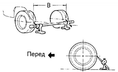
3. Mark the center points of the rear sides of the protectors and measure the distance between them (B) (refer to the accompanying illustration).
The original can be read on the website (toyotaman.ru)
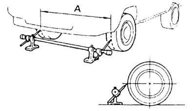
4. Roll the car forward so that the marks placed are moved to the height of the wheel axle, but from the front side of the latter and make a measurement similar to the previous one (A) (refer to the accompanying illustration).
5. The convergence value is determined by subtracting the result of the second measurement (B–A) from the result of the first measurement. Compare the resulting difference with the requirements Specifications.
6. If necessary, loosen the nuts of the tie rod end clamps and adjust the length of the latter accordingly. Make sure that the lengths of the rods remain equal to each other after completing the adjustment.