
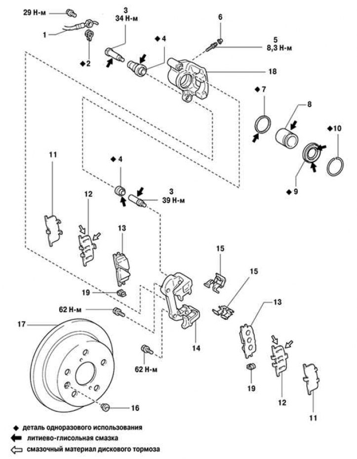
Pic. 6.47. Camry rear wheel disc brakes: 1 - flexible hose; 2 - gasket; 3 - guide pin; 4 - anther; 5 - bleed valve; 6 – a protective cap of the pumping union; 7 - stuffing box; 8 - piston; 9 - piston boot
Disc brake mechanisms of the rear wheels of the Camry car are shown in Figure 6.47.
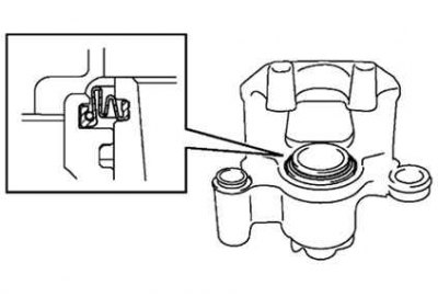
Visual check of pad thickness
Check pad thickness. To do this, raise the car, remove the wheel and look through the inspection hole in the cylinder body.
- Minimum thickness of brake pads: 1mm.
- Limit wear: 2.0 mm.
Drain the brake fluid.
Remove the front wheel and temporarily secure the rim with two nuts.
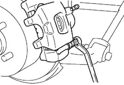
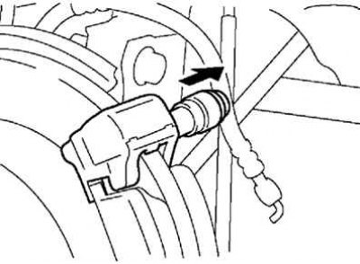
Turn away a bolt and disconnect an arm of a brake hose.
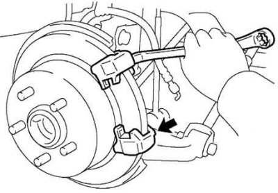
Pic. 6.48. Loosening the caliper bolts
While holding the guide pins, unscrew the caliper mounting bolts (pic. 6.48).
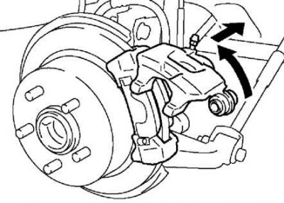
Pic. 6.49. Raising the caliper
Raise the caliper and secure it with wire (pic. 6.49).
Remove two anti-squeak springs, two brake pads, two anti-squeal pads holding plate liners.
Note. Anti-squeak springs and retaining liners can only be reused if they are sufficiently elastic, without deformation, cracks, rust or other defects.
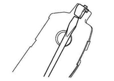
Pic. 6.50. Removing pad wear indicators
Using a thin-blade screwdriver, remove the pad wear indicators (pic. 6.50).
Loosen the mounting bolt and remove the caliper cover from the bracket.
Remove the two brake pads with anti-squeak pads and the two retaining plate bearings.
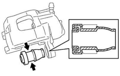
Pic. 6.51. Removing guide pins from caliper housing
Remove guide pin (pic. 6.51).
Pic. 6.52. Removing the caliper body
Remove the 2 bolts and remove the caliper housing from the brake disc (pic. 6.52).
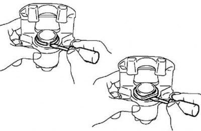
Pic. 6.53. Removing the brake cylinder boot
Using a screwdriver, remove the brake cylinder boot spring ring and boot (pic. 6.53).
Place a rag between piston and cylinder.
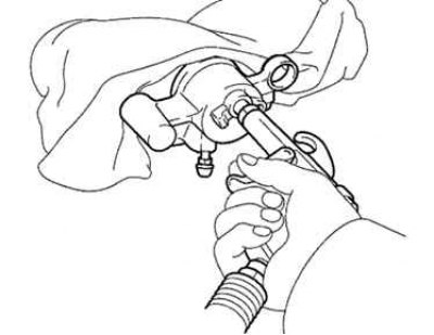
Pic. 6.54. Removing the piston from the cylinder
Using compressed air, remove the piston from the cylinder (pic. 6.54).
Checking the brake pads
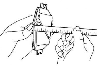
Pic. 6.55. Measuring the thickness of brake pads
Measure the thickness of the brake pads with a ruler (pic. 6.55).
- Standard thickness: 11 mm.
- Minimum thickness: 1.0 mm.
Measuring the thickness of the brake disc
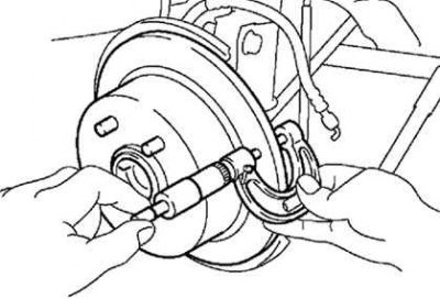
Pic. 6.56. Measuring the thickness of the brake disc
Using a micrometer, measure the thickness of the brake disc (pic. 6.56).
- Standard Thickness: 12mm
- Minimum Thickness: 10.5mm
Replace the disc if the disc thickness is less than the minimum allowable.
Measuring brake disc runout
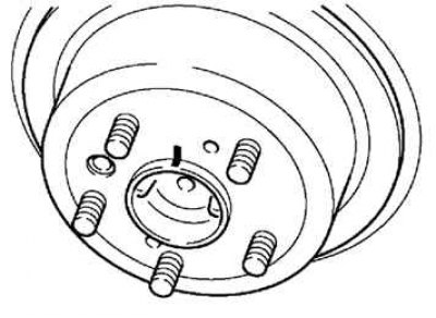
Pic. 6.57. Marking the hub axle bushing and brake disc
Mark the brake disc and wheel hub axle bushing (pic. 6.57).
Attach the brake disc to the wheel hub with wheel nuts (in 2 or more places).
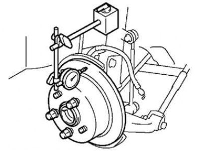
Pic. 6.58. Checking disc runout with an indicator
Check the beat with an indicator (pic. 6.58).
Measuring point:
- at a distance of 10 mm from the outer edge of the disk.
- maximum runout: 0.15mm or less.
Attention! Make sure the end play is 0 mm before taking a measurement.
If the runout is significant, find the point of minimum runout by successively shifting the installation position of the brake disc on the hub by one hole.
Assembly
Pic. 6.59. Installation of a spring ring and a cover of the brake cylinder
Using a screwdriver, install the brake cylinder boot spring ring and boot (pic. 6.59).
When installing the spring ring, be careful not to damage the cover.
Install guide pins.
Tightening torque: 39 Nm.
With socket wrench (8mm) and hammer, install the guide pin boots.
Lubricate the anthers with lithium grease first.
Install the caliper housing mounting bolts.
Tightening torque: 62 Nm.
Pic. 6.60. Installing the boot in the caliper cover
Install the guide pin boot into the caliper cover, after lubricating it with lithium grease (pic. 6.60).
Install the guide pin into the caliper cover.
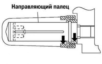
Pic. 6.61. Guide pin installation diagram
Lubricate the finger with lithium grease and, being careful not to damage the anther, insert as shown in Figure 6.61.
Install a new set of brake pads.
Install the caliper cover.
Carry out the rest of the assembly in the reverse order of removal.
Install the rear wheels.
Check the brake fluid level.