
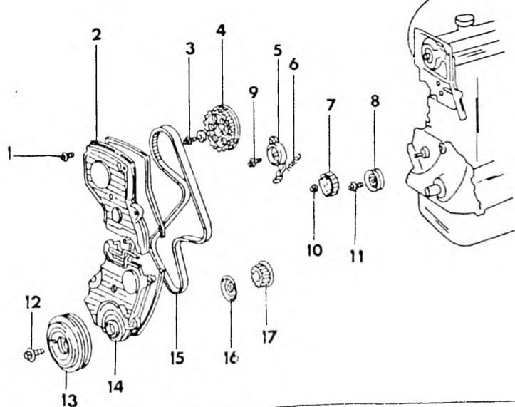
Pic. 110. Parts of the gas distribution mechanism of the 2.0 l engine 1. Cover bolt; 2. Toothed belt upper protective cover; 3. Bolt, 55 Nm; 4. Camshaft gear; 5. Tension roller; 6. Release spring; 7. Oil pump drive gear; 8. Roller; 9. Bolt. 42 Nm; 10. Nut 28 Nm; 11. Bolt, 42 Nm; 12. Bolt, 110 Nm; 13. Crankshaft pulley; 14. Lower protective cover of the toothed belt; 15. Toothed belt; 16. Toothed belt guide washer; 17. Crankshaft gear
Both overhead camshafts are driven by a timing belt and sprockets on each camshaft and on the crankshaft. The timing belt is connected only to the exhaust camshaft, through which the intake camshaft is driven using gears. The crankshaft gear is located behind the crankshaft pulley. The toothed belt is tensioned in the same way as on the 4A-F/E engine.
Removal and installation
Although the work was described when disassembling the engine, it should be described additionally for the case when it is only necessary to replace the timing belt. The drawings associated with the description have already been given on the previous pages. A general view of the mechanism drive is shown here.
- Disconnect the battery and drain the coolant.
- Release the alternator mounting bracket, tilt the alternator and remove the drive belt. Remove the generator.
- After disconnecting the spark plug tips, remove the spark plugs using an extended spark plug wrench.
- Unscrew the 4 cylinder head cover nuts and crush the cover with sealing washers and cover gasket.
- Rotate the crankshaft until the mark on the crankshaft belt pulley aligns with the mark "0" on the scale for setting ignition timing at the front of the engine (see fig. 7). Check that the valves of the first cylinder have clearances. If they are in the shift position, turn the crankshaft one more revolution. To avoid mistakes, observe the camshaft gear. There is a hole on the wheel that should be opposite the mark on the camshaft bearing cap, as can be seen in Figure 26.
- Loosen the belt pulley bolt (hold the flywheel so that the crankshaft cannot turn) and remove the pulley. To press the pulley, you can install pry bars on opposite sides. Otherwise, use a puller as shown in Fig. 8. Two threaded holes allow the puller to be installed on the pulley.
- Unscrew the upper and lower toothed belt covers and remove the gaskets. Unscrew the 5 bolts of the top and 4 bolts of the bottom cover.
- Remove the timing belt guide wheel (pic. 9).
- If the timing belt is to be reinstalled, mark the belt direction arrow and mark on the belt in relation to the camshaft wheel and the crankshaft sprocket, as shown in Figures 27 and 28.
- Loosen the toothed belt tensioner bolt at the front of the engine, press the tensioner by turning it to the left, as shown in Figure 11, and tighten it in the new position. Now the timing belt is free and may be wrinkled. If desired, you can remove the belt tension roller.
- Remove the gear from the crankshaft. If necessary, use two powerful screwdrivers or pry bars, as shown in Figure 29. However, you should place a rag so as not to damage other parts.
- Unscrew the camshaft wheel bolt. Since the shaft rotates in this case, it should be held. Usually, for this, a tool is used, shown in Figure 30, which is inserted into two holes in the wheel, but you can insert a long rod into one of the holes, rotate the wheel until the rod touches the cylinder head and unscrew it after this bolt. Remove the washer and tighten the gear.
- If necessary, remove the oil pump drive gear. It can be kept from turning in the same way as shown for the camshaft gear in Figure 30.
- Checking the timing belt and other parts is done in the same way as on the other engine. Installation of the timing belt was described above.