
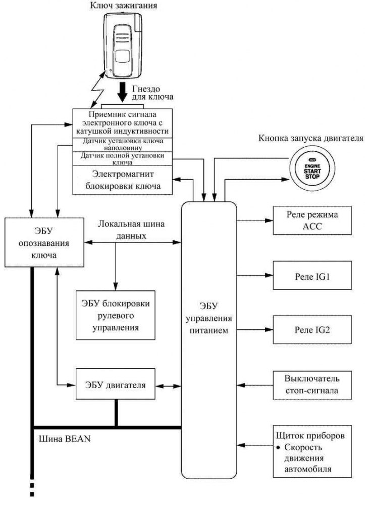
Pic. 1.61. Block diagram of the engine start system
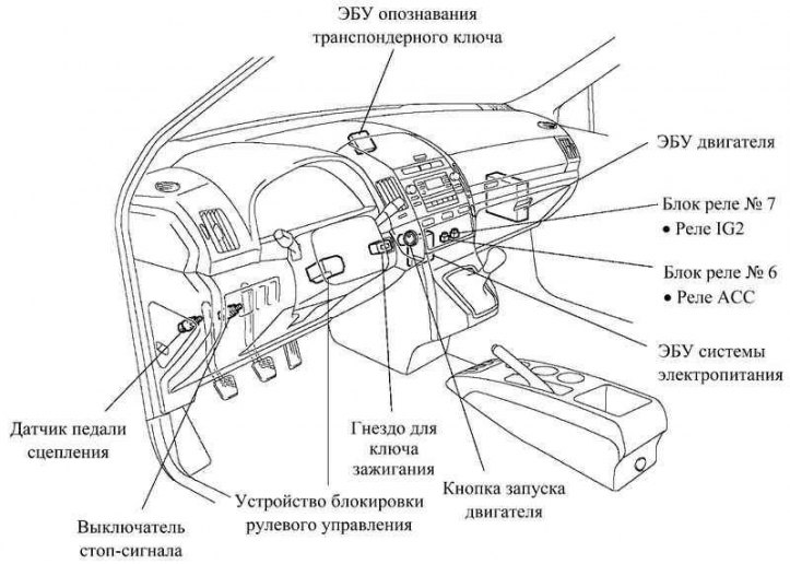
Pic. 1.62. Location of the main components of the engine start system
On previous models, the driver had to insert the key into the ignition switch to turn on the car's electrical equipment and start the engine (with ignition switch). However, the new Corolla Verso instead uses a push-button start system that the driver presses after the key is inserted into a special slot. Thanks to the use of this modern system, the operation of the car is greatly simplified.
The system is standard on all models.
The system consists of the following main components: Power supply ECU, engine start button, ignition key socket, ignition key, ACC relay, IG1 relay, IG2 relay, key recognition ECU and steering lock ECU. The system is controlled by the power supply ECU.
The engine start button works in conjunction with the immobilizer and steering lock system.
Along with the engine start button, the function of semi-automatic control of the starter when starting the engine has been introduced.
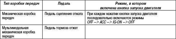
Table 1.26 below shows the power modes that turn on when the engine start button is pressed, depending on whether the brake pedal is pressed or released (on vehicles with M-MT multimodal manual transmission) or clutch pedal (on vehicles with manual transmission).
Table 1.26. Power modes that turn on when the engine start button is pressed
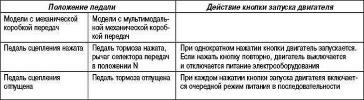
Table 1.27. Engine start conditions
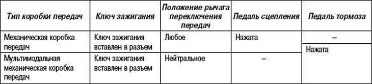
Table 1.28. Conditions under which all vehicle equipment is turned on
Main differences
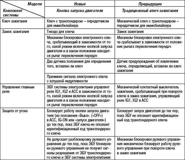
The main differences between the engine start system with a button and the traditional system with a key and ignition lock are described in Table 1.29.
Table 1.29. The main differences between the engine start system with a button
Operating mode of a control lamp
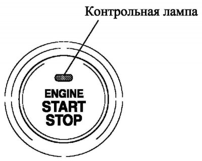
Pic. 1.63. Control lamp of start of the engine
Note. If there is a malfunction in the engine start system with a button, the control lamp flashes yellow. If the engine is turned off in this state, it may not be possible to start it later.
Table 1.31. Operating mode of a control lamp
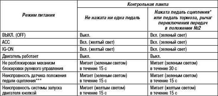
* Vehicles with manual transmission.
** Vehicles with M-MT multimodal manual transmission.
*** If in power mode «Off». («OFF») depress the clutch pedal for more than five minutes, and then open the driver's side door, the indicator lamp on the engine start button will flash. This is not a malfunction.
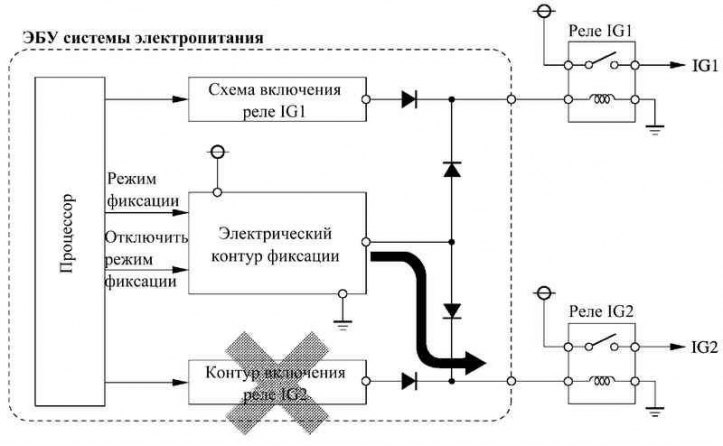
Pic. 1.64. Block diagram of the electrical latching circuit
ECU power supply system
The power supply ECU controls the push button start system according to signals from sensors and other ECUs.
Communication between the power supply ECU and the key recognition ECU is via the BEAN bus (data exchange bus of on-board electronic equipment). In addition, there is a dedicated serial link for independent communication between the key recognition ECU and the steering lock ECU.
The power ECU has an electrical latching circuit that keeps relays IG1 and IG2 energized in the event of a malfunction in the IG1 and IG2 firing circuits. In this way, a power outage is prevented if the relay actuation circuits IG1 and IG2 fail while the vehicle is in motion.
Maintenance recommendation
The power supply mode is permanently stored in the memory of the power supply ECU. Thus, if the power ECU is de-energized, for example, if the battery is removed, then after the battery is connected, the power ECU will restore the previously turned on power mode.
Therefore, if you remove the battery in any power mode other than «Off». («OFF»), power will be supplied to the vehicle's electrical equipment at the same time as power is supplied to the power supply ECU (when connecting the battery). Therefore, before removing the battery, you should turn on the engine start mode with the engine start button «Off». («OFF») and remove the key from the socket.