
Key
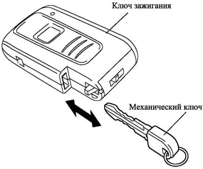
Pic. 1.65. Ignition
The key functions as the ignition key in a conventional system. Until the transponder key recognition ECU recognizes the key ID code, the functions of switching power modes, starting the engine, or unlocking the steering with the engine start button are disabled.
The key transmits an identification code to the transponder key recognition ECU when the key is inserted into the slot.
There is also a mechanical key that can be used in an emergency, if the remote control system for door locks malfunctions (e.g. due to a dead transponder battery). If the remote door locking system does not work, the driver's side door can be unlocked with the mechanical key.
Key socket
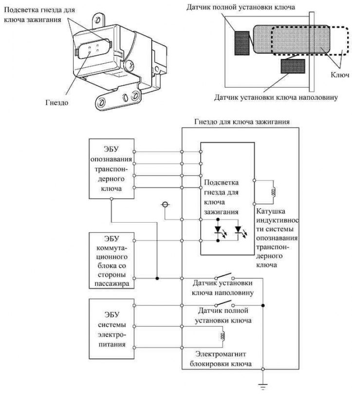
Pic. 1.66. Block diagram and principle of operation of the key socket
The key socket consists of an inductor, a receiver, socket lighting LEDs, a half key setting sensor, a full key setting sensor and a key interlock solenoid.
The half key position sensor, used to determine the position of the key in the slot, is connected to the key recognition ECU and to the passenger side junction box ECU. The key recognition ECU and the passenger side junction box ECU use the signal from the half key setting sensor to check the key code and control the electrical equipment.
Like the half key position sensor, the full key position sensor is also used by the system to determine the position of the key. This sensor is connected to the power supply ECU. The power supply ECU controls the push button start system in accordance with the signals from this sensor.
Warning! Keep your fingers out of the key slot. This may result in injury to the fingers.
Note. The instructions below must be observed, otherwise the key mechanism may be damaged or may not work properly.
- - Handle the key with clean hands.
- - Do not insert the key with force.
- - Only original keys may be inserted into the socket.
- - If the key cannot be removed, do not pull it out with force.
- - Keep water, oil, foreign objects, etc. out of the socket.
- - Do not insert a damp, oily or damaged key into the socket.
- - It is forbidden to stick labels on the key.
- - Do not insert the key in the wrong position.
- - When removing the key from the socket, do not pull on the ring.
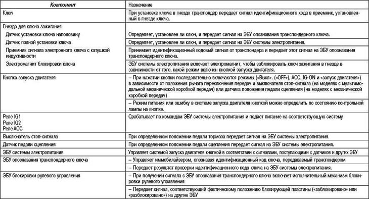
Table 1.30. Purpose of the main components
Key lock solenoid
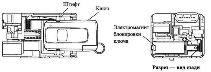
Pic. 1.67. Key lock solenoid
The power supply ECU activates the key lock solenoid according to the power mode of the engine start button and the position of the gear lever (depending on whether parking mode or some other mode is enabled), to secure the key in the slot and prevent accidental removal of the key.
When the key blocking solenoid is turned on, the locking pin, which has entered the hole on the side surface of the key, is blocked. As a result, the key is fixed in the socket.
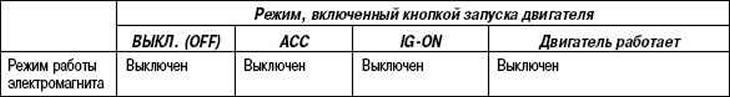
Table 1.32. Key lock solenoid operation mode
Steering lock device (with integrated steering lock ECU)
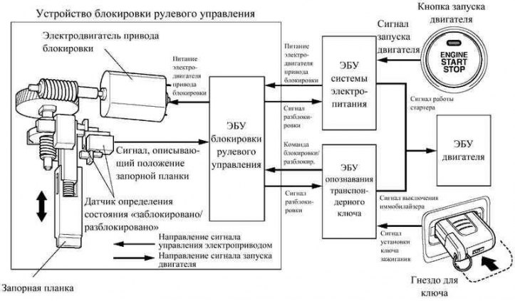
Pic. 1.68. Block diagram of the steering lock system
Along with the engine start button, the vehicle uses a power steering lock system that locks and unlocks the steering shaft. The system unlocks the steering shaft at the moment the engine start button is pressed after the key is inserted into the socket and blocks the steering shaft at the moment the key is removed from the socket, if the mode is turned on «Off». («OFF») or ACC power systems.
The steering lock ECU is built into the steering lock. It controls the electric drive that moves the striker plate.
The steering lock ECU detects the position (locked/unlocked) striker plate and transmits this information to the power supply ECU, key recognition ECU and other ECUs.
As shown in the diagram below, the steering lock ECU is connected to the power supply ECU and the key recognition ECU. Upon receipt of enabling signals from both ECUs, it turns on the electric blocking drive. In addition, the steering lock ECU sends an unlock signal to the power supply ECU and to the key recognition ECU. Upon receiving this signal, the power ECU allows the engine ECU to start the engine, and the key recognition ECU disables the immobilizer.
Maintenance recommendation
It is not possible to replace only the lock ECU in the steering lock device. Therefore, if the lockout ECU is faulty, the steering lock assembly must be replaced.
Design and principle of operation
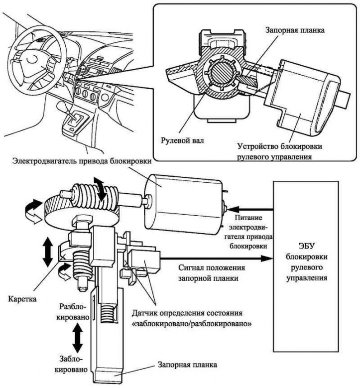
Pic. 1.69. The design and principle of operation of the steering lock system
The steering lock device consists of a steering lock ECU and an electric drive. The electric drive consists of an electric motor that generates the driving force, gears for transmitting the driving force, a steering shaft strike plate and sensors that determine the position of the strike plate.
The gears convert the rotational motion of the motor shaft into the vertical translational motion of the carriage. The strike plate mounted on the carriage also moves in the vertical direction. The tongue of the strap falls into the recess between the gear teeth on the steering shaft, reliably blocking the steering.
The sensor determines the position of the striker plate, i.e. whether the steering shaft is locked. This information is then transmitted to the steering lock ECU.