
Attention! Adjustment of valve clearances is carried out on a cold engine!
Gas engine
Note. To perform this procedure, you will need special tools that can be purchased from Toyota service centers, original auto accessories stores and wholesale markets.
If the clearances in the valve actuator are large, the valves will not open sufficiently. The drive will be noisy and the engine will not pull well, since the cylinders will not be completely filled with the working mixture. The exhaust valves will not open enough to ventilate the cylinders, the remaining gas pressure will prevent a new mixture charge from entering the cylinder. If the gaps are too small, the intake and exhaust valves will not seat tightly when closed. This will impair heat dissipation from heated valves to the head. Due to this, the engine will also lose traction (gases will leak), valves will overheat and burn out.
The clearances in the valve actuator are adjusted by selecting shims of a certain thickness, which are installed in the valve lifters. During manufacture, the valve actuator has some variation within tolerances, therefore, when adjusting the gaps, it is required to install washers that are slightly different in thickness from each other. Toyota produces repair washers of different thicknesses with a pitch of 0.02 mm. For proper valve clearance adjustment, the necessary shims are available from your Toyota dealer.
This procedure requires specialized Toyota tools. To depress the pushrod to get enough clearance to replace the washer (this compresses the valve spring) a tool similar to large flares is used. To fix the pusher in this position, a lever is used, which is installed at a distance between the pusher and the camshaft. A magnetic tool is used to remove the washer, and a micrometer is used to accurately measure its thickness. It is not recommended to adjust the gap if there are no such tools.
The valve adjustment must of course be made as accurate as possible, however, if there is no other possibility, it is better to leave the actuator clearance slightly increased than «pinched», because in the latter case, the valves can burn out. It's better to have a slightly noisy engine than a faulty one.
Examination
1. Disconnect the negative cable from the battery.
Attention! If the stereo system installed in the car is equipped with a security code, before disconnecting the battery, make sure that you have the correct combination to activate the audio system!
2. Empty the cooling system.
3. Disconnect the coils from the spark plugs and remove other components that interfere with the removal of the cylinder head cover.
4. Blow out the candle niches and remove the spark plugs (see Section Checking the condition and replacing spark plugs (gasoline engines)).
Attention! Remember to wear protective goggles when using compressed air!
5. Remove the cover (And) heads (OK) cylinders (see chapter Engine).
6. Bring the piston of the first cylinder to the TDC position of the end of the compression stroke (see chapter Engine).
7. By means of probes of edge type make measurement of backlashes of the valves specified on an accompanying illustration.
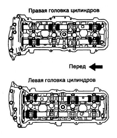
8. Turn the crankshaft one full turn in the normal direction and measure the clearances of the remaining valves (refer to accompanying illustration).
Adjustment
1. After completing the measurements, compare them with the requirements Specifications.
2. On the 2UZ-FE engine, remove the camshaft (see the relevant part of the Chapter Engine).
3. Using a micrometer, measure the thickness of the removed shim. To determine the thickness of a new washer, perform the following calculations:
N=T (A-V)
Where:
T = Thickness of the old shim
A = Measured clearance
V = Required valve clearance
N = Required new shim thickness (see Specifications).
4. Select a new adjusting washer of thickness that allows you to bring the valve clearance as close as possible to the required value. Shims are available in 41 standard sizes ranging from 2.000 to 2.800 mm (No. from 00 to 80) with a step of 0.020 mm.
Note. In some cases, an old washer removed from the pusher of one valve may be suitable for installation on the pusher of another valve that needs adjustment, do not rush to purchase replacement washers.
5. Install the selected adjusting washer on the pusher. Use a feeler gauge of the appropriate thickness to verify that the correct adjustment has been made.
6. Proceed in a similar manner to adjust any valves with out-of-tolerance clearance.
7. Reinstall spark plugs, cover (And) heads (OK) cylinders, protective covers, accelerator cable bracket and other components removed to provide access.
Diesel engine
Examination
1. Remove the air ducts and cylinder head cover.
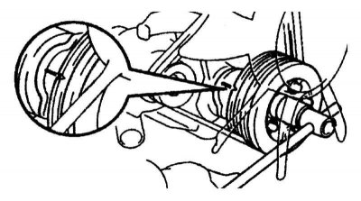
2. Move the piston of the first cylinder to TDC. To do this, by rotating the crankshaft clockwise, align the alignment marks (refer to accompanying illustration). In this case, the cams of the drive of the valves of the first cylinder must be turned up, otherwise turn the crankshaft one more turn. Make sure the #1 cylinder rocker arms are loose and #6 cylinder rocker arms are tight.
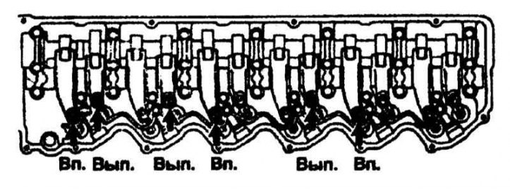
3. Measure a backlash between an adjusting screw of a yoke of the valves specified on an accompanying illustration and the lever of a drive of the valve.
4. Turn the crankshaft one turn and measure the clearance on the remaining valves.
5. Compare measurement results with requirements Specifications and adjust valve clearances if necessary.
Adjustment
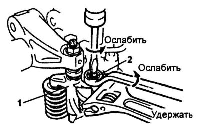
1. Loosen the jam nut on the valve actuator lever (1) and unscrew the adjusting screw (2) so that the latter and the valve stem are completely separated (refer to accompanying illustration).
Note. At the same time, hold the valve actuator lever with an adjustable wrench.
2. Loosen the locknut adjusting screw on the rocker arm.
3. Insert a blade-type feeler gauge between the adjusting screw on the rocker arm and the valve lever. For intake valves, use a 0.20 mm feeler gauge and for exhaust valves, use a 0.50 mm thickness.
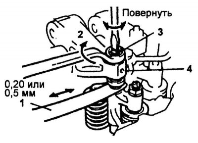
4. Turn the adjusting screw in the rocker until a slight resistance is felt when moving the probe, then fix the adjusting screw with the locknut (refer to accompanying illustration).
5. With the feeler gauge inserted, check that the resistance to its movement does not change when the adjusting screw on the valve drive lever is loosened. Otherwise, go back to paragraph 2.
6. Tighten the adjusting screw on the valve actuator lever and secure it with the locknut when the feeler gauge becomes more resistant.
Note. At the same time, hold the valve actuator lever with an adjustable wrench.
7. Loosen the locknut on the rocker arm.
8. Move the adjusting screw until the feeler gauge moves with very little resistance, then secure the adjusting screw with the locknut.
9. Install the cylinder head cover and previously dismantled parts.