
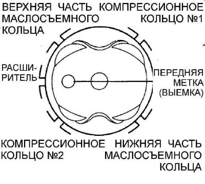
The location of the locks of the piston rings on the piston
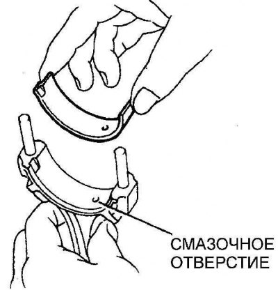
1. Clean the back of the bushing and its mounting location in the connecting rod and the connecting rod cap. In this case, the holes for lubrication in the connecting rod and the liner must be aligned.
2. Install the piston ring locks on the pistons as shown in the figure Location of the piston ring locks on the piston.
3. Remove the pieces of rubber hose from the connecting rod lower head studs.
4. Lubricate pistons and piston rings with clean engine oil.
5. Compress the piston rings on the piston with a piston ring compressor.
6. Rotate the crankshaft to top dead center on cylinder 1 and apply a thin layer of oil to the cylinder walls.
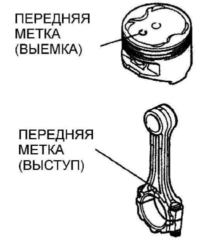 | 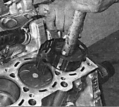 |
7. Insert the piston with the ring compressing tool into the top of the first cylinder. In this case, the notch on the piston must be directed towards the toothed belt.
8. Using a block of wood or a hammer handle, press the piston into the cylinder.
9. Check the alignment of the bottom head of the connecting rod with the neck of the crankshaft. If necessary, tighten the piston with a connecting rod and install the lower head of the connecting rod with an insert on the crankshaft journal.
10. Check the clearance of the connecting rod bearings.
11. Clean the back of the bushing and its mounting location in the connecting rod and the connecting rod cap.
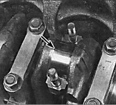
12. Use the Plastigage method to check the operating clearance of the connecting rod bearing. In this case, a round plastic rod is used, which is compressed between the liner and the crankshaft journal. After removing the connecting rod bearing cap, the deformed plastic rod is measured with a special gauge, which is included with Plastigage. The procedure for using Plastigage is as follows. Fit the connecting rods without lubrication to the crankshaft. The crankshaft journals and liners must be perfectly clean and dry. Cut off a few pieces of plastic rod and install them on each crankshaft journal. Install the covers with the bottom liners and tighten the mounting bolts to the required torque.
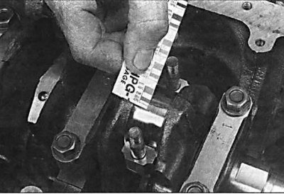
13. Do not rotate the engine crankshaft while measuring the clearance using the Plastigage method. Unscrew the bottom cover of the connecting rod, remove it and attach the scale ruler printed on the package to the deformed plastic rod. By comparing the width of the deformed plastic rod with the reference width on the scale bar, determine the amount of gap. Finally, thoroughly clean any traces of Plastigage from the liners and crankshaft.
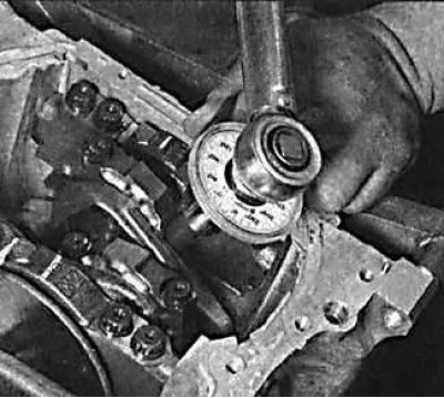
14. Apply a light coat of engine oil to the connecting rod bearing surfaces and install the connecting rod to the crankshaft journal. Establish the bottom cover of a rod and tighten nuts of fastening the demanded moment.
15. Install the remaining pistons with connecting rods in the same way.