



Share information:
Car air conditioner and heater Toyota Camry 3 (XV30)

Air Conditioning and Heating — General Information
Fig. 8.72. Air conditioning system of the Camry: 1 – evaporator; 2 – air conditioning system pressure sensor; 3 – compressor; 4 – evaporator temperature sensor; 5 – Air outlet servomotor; 6 – heater radiator Camry cars...
Fig. 8.72. Air conditioning system of the Camry: 1 – evaporator; 2 – air conditioning system pressure sensor; 3 – compressor; 4 – evaporator temperature sensor; 5 – Air outlet servomotor; 6 – heater radiator Camry cars...

Air conditioner control panel
The air conditioner control panel has a push-button control with a liquid crystal display, which shows the set temperature, blowing mode and fan speed. Fig. 8.74. Air conditioner control panel with automatic control The...
The air conditioner control panel has a push-button control with a liquid crystal display, which shows the set temperature, blowing mode and fan speed. Fig. 8.74. Air conditioner control panel with automatic control The...

Air conditioner unit — design description
Fig. 8.75. Air conditioning unit The air conditioner unit consists of an evaporator and a heater radiator. They are located next to each other, in the longitudinal plane relative to the car, due to which the air...
Fig. 8.75. Air conditioning unit The air conditioner unit consists of an evaporator and a heater radiator. They are located next to each other, in the longitudinal plane relative to the car, due to which the air...
Heater radiator — design description
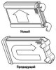
Fig. 8.76. Heater radiator of the new Camry A new compact, lightweight and efficient straight-through aluminum heater radiator is used (Fig. 8.76).
Fig. 8.76. Heater radiator of the new Camry A new compact, lightweight and efficient straight-through aluminum heater radiator is used (Fig. 8.76).

Evaporator — design description
Fig. 8.77. Evaporator structure: 1 – inner plate; 2 - antibacterial substance; 3 – nylon; 4 – chromatic layer; 5 – aluminum matrix Since 2002, the Camry has used a new type of evaporator (Fig. 8.77), which combines a...
Fig. 8.77. Evaporator structure: 1 – inner plate; 2 - antibacterial substance; 3 – nylon; 4 – chromatic layer; 5 – aluminum matrix Since 2002, the Camry has used a new type of evaporator (Fig. 8.77), which combines a...

Evaporator pre-cooling cycle
Fig. 8.78. Schematic diagram of the evaporator pre-cooling cycle: 1 – multi-flow evaporator; 2 – condensation element; 3 – gaseous refrigerant; 4 – liquid refrigerant; 5 – modulator; 5 – hypothermia element In the...
Fig. 8.78. Schematic diagram of the evaporator pre-cooling cycle: 1 – multi-flow evaporator; 2 – condensation element; 3 – gaseous refrigerant; 4 – liquid refrigerant; 5 – modulator; 5 – hypothermia element In the...

Air Conditioner Compressor — Design Description
Fig. 8.79. Air conditioning compressor: 1 – inclined washer; 2 – piston; 3 – piston shaft; 4 – inclined washer chamber The Camry uses a compact, low-noise swash plate compressor (Fig. 8.79).
Fig. 8.79. Air conditioning compressor: 1 – inclined washer; 2 – piston; 3 – piston shaft; 4 – inclined washer chamber The Camry uses a compact, low-noise swash plate compressor (Fig. 8.79).

Quick release coupling
Fig. 8.80. Quick-release coupling: 1 – clamp; 2 – air conditioner tube To connect the air conditioner pipes that run from the engine compartment to the passenger compartment, instead of the threaded coupling used on the...
Fig. 8.80. Quick-release coupling: 1 – clamp; 2 – air conditioner tube To connect the air conditioner pipes that run from the engine compartment to the passenger compartment, instead of the threaded coupling used on the...

Air filter — replacement
Fig. 8.81. Air filter: 1 – filter housing The cabin air filter (Fig. 8.81) is made of polyester and can be easily disposed of as a flammable material. This feature is dictated by modern environmental protection...
Fig. 8.81. Air filter: 1 – filter housing The cabin air filter (Fig. 8.81) is made of polyester and can be easily disposed of as a flammable material. This feature is dictated by modern environmental protection...

Electronic control unit of air conditioner
The control functions of the air conditioner electronic control unit are presented in Table 8.4. Table 8.4. Control functions of the air conditioner electronic control unit
The control functions of the air conditioner electronic control unit are presented in Table 8.4. Table 8.4. Control functions of the air conditioner electronic control unit

Self-diagnosis of the air conditioner control unit
Fig. 8.82. Self-diagnostic function startup diagram The air conditioner control unit has a self-diagnostic function. Information about failures in the air conditioning system is stored in the system memory in the form...
Fig. 8.82. Self-diagnostic function startup diagram The air conditioner control unit has a self-diagnostic function. Information about failures in the air conditioning system is stored in the system memory in the form...
This section is available on: russian, bulgarian, belarusian, ukrainian, serbian, croatian, romanian, polish, slovak, hungarian
Similar sections for other Toyota models
➥ Air conditioning and heater Toyota Carina T190 (1992-1996)
Link in different formats to this article
TEXTHTMLBB Code
- User manual
- Vehicle description
- Keys, locks and alarms
- Governing bodies
- Salon equipment
- Driving and operation
- Maintenance
- Power unit
- 4-cylinder engine
- Control system (I4)
- Engine overhaul (I4)
- 6-cylinder engine
- Control system (V6)
- Engine overhaul (V6)
- Transmission
- Clutch
- Mechanical gearbox
- Automatic gearbox
- Drive mechanism
- Chassis, running gear
- Wheels and tires
- Car suspension
- Steering
- Brake system
- Body and interior
- Exterior (external elements)
- Doors, locks and windows
- Air conditioning and heater
- Electrical equipment
- Equipment and devices
- Power devices
- Electrical circuits
- General information
- Controls and instruments
- Driving and operation
- Daily care
- Maintenance
- Power unit
- 4-cylinder engine
- 6-cylinder engine
- Engine overhaul
- Engine electrical equipment
- Cooling system
- Heating and ventilation
- Fuel system
- Exhaust system
- Transmission
- Mechanical gearbox
- Automatic gearbox
- Clutch
- Chassis, running gear
- Suspension and axle shafts
- Steering
- Brake system
- Body and interior
- Exterior (external elements)
- Interior (internal elements)
- Doors, locks and windows
- Electrical equipment
- Equipment and devices
- Electrical circuits
- General information
- User manual
- Maintenance
- Power unit
- 4-cylinder engine
- 6-cylinder engine
- Overhaul of engines
- Cooling and heating
- Fuel system
- Engine electrical equipment
- Control system
- Transmission
- Mechanical gearbox
- Automatic gearbox
- Clutch and drive shafts
- Chassis, running gear
- Brake system
- Car suspension
- Steering
- Body and interior
- Exterior (external elements)
- Interior (internal elements)
- Doors, locks and windows
- Electrical equipment
- Equipment and devices
- Headlights and lighting
- Electrical circuits
- General information
- User manual
- Maintenance
- Power unit
- Petrol engines
- Diesel engines
- Engine overhaul
- Cooling and lubrication system
- Fuel system (diesel)
- Fuel injection (petrol)
- Engine electrical equipment
- Transmission
- Clutch and cardan
- Automatic gearbox
- Chassis, running gear
- Front suspension
- Rear suspension
- Steering
- Brake system
- Body and interior
- Body elements
- Air conditioning and heater
- SRS security system
- Electrical equipment
- Equipment and devices
- Electrical circuits