



Share information:
Battery, alternator and starter Toyota Camry 3 (XV30)

Battery — General Information
The vehicle covered in this manual has a 12-volt electrical system. The body ground is connected to the negative terminal of the battery. The battery is located in the engine compartment or under the rear seat (models...
The vehicle covered in this manual has a 12-volt electrical system. The body ground is connected to the negative terminal of the battery. The battery is located in the engine compartment or under the rear seat (models...
Charging the battery
A battery with a green dot indicates that charging is not required until the battery is discharged, such as when starting a cold engine. When charging a battery with sealed terminals outside the vehicle, install an...
A battery with a green dot indicates that charging is not required until the battery is discharged, such as when starting a cold engine. When charging a battery with sealed terminals outside the vehicle, install an...

Charging a completely discharged battery
Use the following procedure to recharge a completely discharged battery. Measure the voltage at the battery terminals with an accurate voltmeter. If the measured value is below 10 V, the charging current will be very...
Use the following procedure to recharge a completely discharged battery. Measure the voltage at the battery terminals with an accurate voltmeter. If the measured value is below 10 V, the charging current will be very...
Battery care
To ensure that your battery lasts longer and maintains its maximum capacity, the following conditions must be met. The battery and its surrounding parts should be kept clean. The surface of the battery should always be...
To ensure that your battery lasts longer and maintains its maximum capacity, the following conditions must be met. The battery and its surrounding parts should be kept clean. The surface of the battery should always be...
Checking a fully charged battery
Set the ammeter (with a measurement limit of 0-5 mA and 0-5 A) to the highest measurement limit. Connect the ammeter between the negative terminal of the battery and the ground cable. Connect the positive wire of the...
Set the ammeter (with a measurement limit of 0-5 mA and 0-5 A) to the highest measurement limit. Connect the ammeter between the negative terminal of the battery and the ground cable. Connect the positive wire of the...
Removal and installation the battery
When the battery is disconnected, the memory of the central control unit of the engine and gearbox, the anti-lock braking system, and a number of other electrical devices, such as the radio and clock, are erased of the...
When the battery is disconnected, the memory of the central control unit of the engine and gearbox, the anti-lock braking system, and a number of other electrical devices, such as the radio and clock, are erased of the...
Electrical power supply system — general information
The power supply system consists of a generator, a voltage regulator and a battery. When these devices work together, they supply power to such consumers of electricity as ignition, headlights, radio, etc. The vehicles...
The power supply system consists of a generator, a voltage regulator and a battery. When these devices work together, they supply power to such consumers of electricity as ignition, headlights, radio, etc. The vehicles...

Generator — design description
Fig. 7.1. Components of the Segment Conductor generator: 1 – pulley; 2 – front cover; 3 – rotor; 4 – slip ring; 5 – rectifier block housing; 6 – rectifier block; 7 – output isolator; 8 – voltage regulator relay...
Fig. 7.1. Components of the Segment Conductor generator: 1 – pulley; 2 – front cover; 3 – rotor; 4 – slip ring; 5 – rectifier block housing; 6 – rectifier block; 7 – output isolator; 8 – voltage regulator relay...

Checking the generator on the car
Check the density and level of electrolyte in each compartment of the battery. Fig. 7.2. Checking the battery charge level using a voltmeter Check the reliability of the battery terminal connections and make sure there...
Check the density and level of electrolyte in each compartment of the battery. Fig. 7.2. Checking the battery charge level using a voltmeter Check the reliability of the battery terminal connections and make sure there...

Checking the drive belt of the attachments
Fig. 7.4. Example of wear of the drive belt of attachment units Check the drive belt of the attachment units for wear and damage. If defects are found, replace the belt (Fig. 7.4). Note: Separation of rubber from the...
Fig. 7.4. Example of wear of the drive belt of attachment units Check the drive belt of the attachment units for wear and damage. If defects are found, replace the belt (Fig. 7.4). Note: Separation of rubber from the...

Checking the generator electrical circuit at idle speed
Note: If you have a tester for checking the generator and battery, connect it in accordance with the manufacturer's instructions. If you don't have a tester, do the following: disconnect the wire from the generator...
Note: If you have a tester for checking the generator and battery, connect it in accordance with the manufacturer's instructions. If you don't have a tester, do the following: disconnect the wire from the generator...

Removal the generator (models with engine 1 and 2 AZ-FE)
Remove the drive belt by loosening the support, lock and adjusting bolts. Disconnect the generator connector, loosen the nut and disconnect the generator wiring. Disconnect the wiring clamp from the generator. Fig. 7.9....
Remove the drive belt by loosening the support, lock and adjusting bolts. Disconnect the generator connector, loosen the nut and disconnect the generator wiring. Disconnect the wiring clamp from the generator. Fig. 7.9....

Generator Installation (Models with 1 and 2 AZ-FE Engines)
Install the generator on the bracket. Install the generator mounting support and lock bolts, tighten them, but do not tighten them completely. Fig. 7.10. Generator installation (models with engine 1 and 2 AZ-FE) Connect...
Install the generator on the bracket. Install the generator mounting support and lock bolts, tighten them, but do not tighten them completely. Fig. 7.10. Generator installation (models with engine 1 and 2 AZ-FE) Connect...

Removal the generator (models with 1MZ-FE engine)
Disconnect the generator wire connector. Remove the mounting nut and disconnect the lead wire from clamp B. Loosen bolts A and B. Loosen bolt C to reduce the drive belt tension. Fig. 7.11. Removing the generator (models...
Disconnect the generator wire connector. Remove the mounting nut and disconnect the lead wire from clamp B. Loosen bolts A and B. Loosen bolt C to reduce the drive belt tension. Fig. 7.11. Removing the generator (models...
Generator installation (models with 1MZ-FE engine)
Install the generator. Temporarily install bolts A and B. Connect the generator wire connector. Adjust the drive belt tension by tightening adjusting bolt C. Tighten bolts A and B. Tightening torque: bolt A - 58 Nm;...
Install the generator. Temporarily install bolts A and B. Connect the generator wire connector. Adjust the drive belt tension by tightening adjusting bolt C. Tighten bolts A and B. Tightening torque: bolt A - 58 Nm;...

Disassembling the generator
Unscrew the nut and remove the terminal insulator. Fig. 7.12. Removing the rectifier plate Remove the rectifier plate (Fig. 7.12). Unscrew the three cover mounting nuts and remove the generator cover from the rectifier...
Unscrew the nut and remove the terminal insulator. Fig. 7.12. Removing the rectifier plate Remove the rectifier plate (Fig. 7.12). Unscrew the three cover mounting nuts and remove the generator cover from the rectifier...
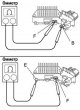
Checking the voltage regulator relay
Fig. 7.22. Checking the voltage regulator relay Using an ohmmeter, check the continuity between diodes F and B (Fig. 7.22). Caution! When the positive and negative poles between terminals F and B are connected in a...
Fig. 7.22. Checking the voltage regulator relay Using an ohmmeter, check the continuity between diodes F and B (Fig. 7.22). Caution! When the positive and negative poles between terminals F and B are connected in a...

Checking the generator rotor
Check for a break in the excitation winding. Fig. 7.23. Checking the resistance between the slip rings Using an ohmmeter, measure the resistance between the contact rings (Fig. 7.23). Nominal resistance (in "cold"...
Check for a break in the excitation winding. Fig. 7.23. Checking the resistance between the slip rings Using an ohmmeter, measure the resistance between the contact rings (Fig. 7.23). Nominal resistance (in "cold"...

Checking the generator slip rings
Check the working surfaces of the contact rings. They should not have any burrs or chips. Fig. 7.25. Measuring the diameter of slip rings Use a caliper to measure the diameter of the contact rings (Fig. 7.25). Standard...
Check the working surfaces of the contact rings. They should not have any burrs or chips. Fig. 7.25. Measuring the diameter of slip rings Use a caliper to measure the diameter of the contact rings (Fig. 7.25). Standard...

Checking the generator rectifier block
Check the positive valve. Fig. 7.26. Circuit for checking the conductivity of the rectifier block contacts Connect the negative probe of the ohmmeter to the positive terminal of the rectifier unit, and connect the...
Check the positive valve. Fig. 7.26. Circuit for checking the conductivity of the rectifier block contacts Connect the negative probe of the ohmmeter to the positive terminal of the rectifier unit, and connect the...

Checking the generator brushes
Fig. 7.27. Measuring the length of the protruding part of the brush Measure the length of the protruding part of the brushes (Fig. 7.27). Standard length: 9.5-11.5mm. Minimum allowable: 1.5 mm. If the brush length is...
Fig. 7.27. Measuring the length of the protruding part of the brush Measure the length of the protruding part of the brushes (Fig. 7.27). Standard length: 9.5-11.5mm. Minimum allowable: 1.5 mm. If the brush length is...

Checking the generator bearings
Check the front bearing. Check that the front bearing moves smoothly and without binding. Replace the bearing if necessary. Remove the four screws and remove the bearing holder. Fig. 7.28. Pressing out the front bearing...
Check the front bearing. Check that the front bearing moves smoothly and without binding. Replace the bearing if necessary. Remove the four screws and remove the bearing holder. Fig. 7.28. Pressing out the front bearing...

Generator assembly
Install the drive side generator cover onto the rotor. Install the washer. Using a plastic-headed hammer, install the rectifier housing. Secure the housing with four nuts. Tightening torque: 4.5–5.4 Nm. Fig. 7.29....
Install the drive side generator cover onto the rotor. Install the washer. Using a plastic-headed hammer, install the rectifier housing. Secure the housing with four nuts. Tightening torque: 4.5–5.4 Nm. Fig. 7.29....

Starter — General Information
The starting system includes a starter powered by a battery. The starter consists of a motor, a traction relay, an ignition switch, and a locking switch (only on cars with automatic transmission), connecting wires and...
The starting system includes a starter powered by a battery. The starter consists of a motor, a traction relay, an ignition switch, and a locking switch (only on cars with automatic transmission), connecting wires and...

New PS starter for Camry
Fig. 7.33. Comparative structural diagram of a conventional starter and a starter with a planetary gearbox Camry cars are equipped with a PS starter (electric motor with planetary gearbox see Fig. 7.33). Since the PS...
Fig. 7.33. Comparative structural diagram of a conventional starter and a starter with a planetary gearbox Camry cars are equipped with a PS starter (electric motor with planetary gearbox see Fig. 7.33). Since the PS...

Removal and installation the starter (models with engine 1 and 2 AZ-FE)
Disconnect the wires from the battery terminals. Remove the battery with the support. Remove the air filter assembly with the bracket. Disconnect the starter connector. Unscrew the nut and disconnect terminal 30 of the...
Disconnect the wires from the battery terminals. Remove the battery with the support. Remove the air filter assembly with the bracket. Disconnect the starter connector. Unscrew the nut and disconnect terminal 30 of the...

Removal and installation the starter (models with 1MZ-FE engine)
Disconnect the wires from the battery terminals. Remove the battery with the support. Remove the air filter assembly with the bracket. Disconnect the starter connector. Unscrew the nut and disconnect terminal 30 of the...
Disconnect the wires from the battery terminals. Remove the battery with the support. Remove the air filter assembly with the bracket. Disconnect the starter connector. Unscrew the nut and disconnect terminal 30 of the...

Checking the starter operation
Attention! The check must be performed within 3–5 s to avoid damage to the stator winding. Checking the pull-in winding of the traction relay Disconnect the wire from the starter terminal "C". Fig. 7.36. Connecting the...
Attention! The check must be performed within 3–5 s to avoid damage to the stator winding. Checking the pull-in winding of the traction relay Disconnect the wire from the starter terminal "C". Fig. 7.36. Connecting the...

Checking the starter relay
Fig. 7.40. Starter relay terminals Using an ohmmeter, check for continuity between terminals "1" and "2" (Fig. 7.40). Using an ohmmeter, make sure there is no continuity between terminals "3" and "5". If the signal does...
Fig. 7.40. Starter relay terminals Using an ohmmeter, check for continuity between terminals "1" and "2" (Fig. 7.40). Using an ohmmeter, make sure there is no continuity between terminals "3" and "5". If the signal does...

Disassembling the starter
Remove the starter housing complete with the starter winding and anchor from the traction relay housing. Fig. 7.41. Removing the traction relay wire terminal Unscrew the nut and disconnect the wire terminal from the...
Remove the starter housing complete with the starter winding and anchor from the traction relay housing. Fig. 7.41. Removing the traction relay wire terminal Unscrew the nut and disconnect the wire terminal from the...

Checking the starter anchor
Fig. 7.47. Measuring the resistance between the collector lamellas Using an ohmmeter, measure the resistance between the collector lamellas. The resistance should tend to 0, i.e. the circuit should be closed (Fig....
Fig. 7.47. Measuring the resistance between the collector lamellas Using an ohmmeter, measure the resistance between the collector lamellas. The resistance should tend to 0, i.e. the circuit should be closed (Fig....

Checking the starter manifold
Inspect the working surfaces of the collector lamellas; if they are dirty or burnt, clean the working surfaces with #400 sandpaper or turn the collector on a lathe. Fig. 7.49. Measuring collector runout Mount the anchor...
Inspect the working surfaces of the collector lamellas; if they are dirty or burnt, clean the working surfaces with #400 sandpaper or turn the collector on a lathe. Fig. 7.49. Measuring collector runout Mount the anchor...

Checking the starter brush holder
Check the brush holder insulation. Fig. 7.52. Checking the brush holder insulation Using an ohmmeter, make sure that the resistance between the positive "+" and negative "-" brush holder tends to infinity, i.e. the...
Check the brush holder insulation. Fig. 7.52. Checking the brush holder insulation Using an ohmmeter, make sure that the resistance between the positive "+" and negative "-" brush holder tends to infinity, i.e. the...
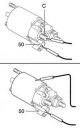
Checking the starter traction relay
Fig. 7.53. Checking the traction relay Check for a break in the pull-in winding circuit. Measure the resistance between terminals "50" and "C" using an ohmmeter (Fig. 7.53). If the resistance tends to infinity, i.e. the...
Fig. 7.53. Checking the traction relay Check for a break in the pull-in winding circuit. Measure the resistance between terminals "50" and "C" using an ohmmeter (Fig. 7.53). If the resistance tends to infinity, i.e. the...

Assembling the starter
When assembling the starter, use high temperature grease to lubricate the bearings and gears. Lubricate the starter clutch shaft with grease. Using needle-nose pliers, install the spring ring onto the coupling shaft....
When assembling the starter, use high temperature grease to lubricate the bearings and gears. Lubricate the starter clutch shaft with grease. Using needle-nose pliers, install the spring ring onto the coupling shaft....
This section is available on: russian, bulgarian, belarusian, ukrainian, serbian, croatian, romanian, polish, slovak, hungarian
Similar sections for other Toyota models
➥ Power devices Toyota RAV 4 XA10 (1994-2000)
➥ Power devices Toyota Corolla Verso 3 (2004-2009)
➥ Starting and charging system Toyota Dyna Y50/Y60 (1984-1995)
➥ Charge and start system Toyota Cruiser 70 (1985-1996, diesel)
➥ Power devices Toyota Carina T170 (1988-1992)
➥ Power devices Toyota 4Runner N120 (1989-1995)
Link in different formats to this article
TEXTHTMLBB Code
- User manual
- Vehicle description
- Keys, locks and alarms
- Governing bodies
- Salon equipment
- Driving and operation
- Maintenance
- Power unit
- 4-cylinder engine
- Control system (I4)
- Engine overhaul (I4)
- 6-cylinder engine
- Control system (V6)
- Engine overhaul (V6)
- Transmission
- Clutch
- Mechanical gearbox
- Automatic gearbox
- Drive mechanism
- Chassis, running gear
- Wheels and tires
- Car suspension
- Steering
- Brake system
- Body and interior
- Exterior (external elements)
- Doors, locks and windows
- Air conditioning and heater
- Electrical equipment
- Equipment and devices
- Power devices
- Electrical circuits
- General information
- Controls and instruments
- Driving and operation
- Daily care
- Maintenance
- Power unit
- 4-cylinder engine
- 6-cylinder engine
- Engine overhaul
- Engine electrical equipment
- Cooling system
- Heating and ventilation
- Fuel system
- Exhaust system
- Transmission
- Mechanical gearbox
- Automatic gearbox
- Clutch
- Chassis, running gear
- Suspension and axle shafts
- Steering
- Brake system
- Body and interior
- Exterior (external elements)
- Interior (internal elements)
- Doors, locks and windows
- Electrical equipment
- Equipment and devices
- Electrical circuits
- General information
- User manual
- Maintenance
- Power unit
- 4-cylinder engine
- 6-cylinder engine
- Overhaul of engines
- Cooling and heating
- Fuel system
- Engine electrical equipment
- Control system
- Transmission
- Mechanical gearbox
- Automatic gearbox
- Clutch and drive shafts
- Chassis, running gear
- Brake system
- Car suspension
- Steering
- Body and interior
- Exterior (external elements)
- Interior (internal elements)
- Doors, locks and windows
- Electrical equipment
- Equipment and devices
- Headlights and lighting
- Electrical circuits
- General information
- User manual
- Maintenance
- Power unit
- Petrol engines
- Diesel engines
- Engine overhaul
- Cooling and lubrication system
- Fuel system (diesel)
- Fuel injection (petrol)
- Engine electrical equipment
- Transmission
- Clutch and cardan
- Automatic gearbox
- Chassis, running gear
- Front suspension
- Rear suspension
- Steering
- Brake system
- Body and interior
- Body elements
- Air conditioning and heater
- SRS security system
- Electrical equipment
- Equipment and devices
- Electrical circuits