




Share information:
Fuel injection for gasoline engines Toyota Vista 4 (V40)

Fuel injection description
The fuel injection system consists of three main subsystems: fuel supply, air supply and electronic control. Fuel system Fuel is supplied by the fuel pump at a constant pressure difference (284 kPa) through the filter...
The fuel injection system consists of three main subsystems: fuel supply, air supply and electronic control. Fuel system Fuel is supplied by the fuel pump at a constant pressure difference (284 kPa) through the filter...

Precautionary measures
Precautions when servicing electrical equipment 1. Check that the engine settings are correct (see chapter " Maintenance and general check and adjustment procedures "). 2 Precautions when connecting devices. a) Use the...
Precautions when servicing electrical equipment 1. Check that the engine settings are correct (see chapter " Maintenance and general check and adjustment procedures "). 2 Precautions when connecting devices. a) Use the...

Self-diagnosis system
Description The electronic control unit has a built-in self-diagnostic system, which continuously monitors the engine condition using sensor signals. If a malfunction is detected, this system identifies it and informs...
Description The electronic control unit has a built-in self-diagnostic system, which continuously monitors the engine condition using sensor signals. If a malfunction is detected, this system identifies it and informs...

Diagnosing faults using a road test
The use of the road test has the following objectives: a) Reproduction (simulation) of driving modes in which this diagnostic code is detected. b) Ensure that the repair work has been completed to the fullest extent,...
The use of the road test has the following objectives: a) Reproduction (simulation) of driving modes in which this diagnostic code is detected. b) Ensure that the repair work has been completed to the fullest extent,...

Troubleshooting with a Voltmeter
Note. Each system has its own troubleshooting procedures, which are outlined in this manual. These procedures may change slightly from time to time. However, the methods outlined in this manual are generally sufficient...
Note. Each system has its own troubleshooting procedures, which are outlined in this manual. These procedures may change slightly from time to time. However, the methods outlined in this manual are generally sufficient...

Electronic Fuel Injection Control System Test Procedure
Prerequisites. a) Disconnect the connectors from the electronic control unit. b) Remove the clips as shown in the figure, which will allow easy connection of the tester probes. Note: Be careful with elements "A" and "B"...
Prerequisites. a) Disconnect the connectors from the electronic control unit. b) Remove the clips as shown in the figure, which will allow easy connection of the tester probes. Note: Be careful with elements "A" and "B"...

Electronic control unit outputs
3S-FE (4WD with automatic transmission). 3S-FE (4WD with manual transmission). 3S-FE (front wheel drive, with TRC system). 3S-FE (front wheel drive, without TRC system). 4S-FE (with automatic transmission). 4S-FE (with...
3S-FE (4WD with automatic transmission). 3S-FE (4WD with manual transmission). 3S-FE (front wheel drive, with TRC system). 3S-FE (front wheel drive, without TRC system). 4S-FE (with automatic transmission). 4S-FE (with...

Fuel pump
Checking on the engine 1. Check the operation of the fuel pump. a) Turn on the ignition. Note: Do not start the engine. b) Short-circuit the "+B" and "FP" terminals of the diagnostic connector with a jumper c) Check for...
Checking on the engine 1. Check the operation of the fuel pump. a) Turn on the ignition. Note: Do not start the engine. b) Short-circuit the "+B" and "FP" terminals of the diagnostic connector with a jumper c) Check for...

Fuel pressure regulator
Checking on the engine Check the fuel pressure (see " Checking the fuel pump "). Removal and installation the regulator 1 Disconnect the cable from the negative (-) battery terminal. 2. Disconnect the power steering...
Checking on the engine Check the fuel pressure (see " Checking the fuel pump "). Removal and installation the regulator 1 Disconnect the cable from the negative (-) battery terminal. 2. Disconnect the power steering...

Injectors — removal and installation
Checking on the engine 1. Check the functionality of the injectors by ear. a) With the engine running or when turning it over with the starter, use a phonendoscope to check by ear (by the sound of injected fuel) in the...
Checking on the engine 1. Check the functionality of the injectors by ear. a) With the engine running or when turning it over with the starter, use a phonendoscope to check by ear (by the sound of injected fuel) in the...

Air supply system
Vacuum line diagram (since 1996). 1 - fuel pressure regulator, 2 and 5 - idle speed increase system hoses No.3 and No.1 respectively, 3 - absolute pressure sensor in the intake manifold, 4 - electro-pneumatic valve, 6 -...
Vacuum line diagram (since 1996). 1 - fuel pressure regulator, 2 and 5 - idle speed increase system hoses No.3 and No.1 respectively, 3 - absolute pressure sensor in the intake manifold, 4 - electro-pneumatic valve, 6 -...

Throttle body
Check on the car 1. Check the throttle body. a) Check the smooth operation of the damper drive. Cars with automatic transmission Removal the throttle body 1. Drain the coolant from the engine. 2. Disconnect the...
Check on the car 1. Check the throttle body. a) Check the smooth operation of the damper drive. Cars with automatic transmission Removal the throttle body 1. Drain the coolant from the engine. 2. Disconnect the...

Valve of the idle speed control system
Checking on the engine 1. Check the operation of the valve. a) Initial conditions: the engine is warmed up to normal operating temperature, the idle speed is adjusted correctly, the gear shift lever or automatic...
Checking on the engine 1. Check the operation of the valve. a) Initial conditions: the engine is warmed up to normal operating temperature, the idle speed is adjusted correctly, the gear shift lever or automatic...

Electronic control system
Fuel injection system main relay 1. Remove the main fuel injection system relay. 2. Check the resistance of the relay winding. a) Using an ohmmeter, check for conductivity between terminals "1" and "3" (resistance -...
Fuel injection system main relay 1. Remove the main fuel injection system relay. 2. Check the resistance of the relay winding. a) Using an ohmmeter, check for conductivity between terminals "1" and "3" (resistance -...
Traction Control (TRC)
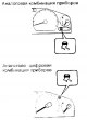
Check on the car Checking the TRC Operation Indicator Turn the ignition on (ON). Check that the TRC operation indicator light is on for about 3 seconds. Checking the "TRC OFF" indicator 1. Turn on the ignition (ON)....
Check on the car Checking the TRC Operation Indicator Turn the ignition on (ON). Check that the TRC operation indicator light is on for about 3 seconds. Checking the "TRC OFF" indicator 1. Turn on the ignition (ON)....
This section is available on: russian, bulgarian, belarusian, ukrainian, serbian, croatian, romanian, polish, slovak, hungarian
Similar sections for other Toyota models
➥ Fuel injection system Toyota Carina T190 (1992-1996)
➥ Fuel injection system Toyota Duet (1998-2004)
➥ Fuel injection (petrol) Toyota Corona T190 (1992-1997)
➥ Fuel system (injector) Toyota Cruiser 60/80 (1980-1997, petrol)
➥ Fuel supply (injector) Toyota Corolla E80 (1983-1990)
Link in different formats to this article
TEXTHTMLBB Code
- User manual
- Vehicle description
- Keys, locks and alarms
- Governing bodies
- Salon equipment
- Driving and operation
- Maintenance
- Power unit
- 4-cylinder engine
- Control system (I4)
- Engine overhaul (I4)
- 6-cylinder engine
- Control system (V6)
- Engine overhaul (V6)
- Transmission
- Clutch
- Mechanical gearbox
- Automatic gearbox
- Drive mechanism
- Chassis, running gear
- Wheels and tires
- Car suspension
- Steering
- Brake system
- Body and interior
- Exterior (external elements)
- Doors, locks and windows
- Air conditioning and heater
- Electrical equipment
- Equipment and devices
- Power devices
- Electrical circuits
- General information
- Controls and instruments
- Driving and operation
- Daily care
- Maintenance
- Power unit
- 4-cylinder engine
- 6-cylinder engine
- Engine overhaul
- Engine electrical equipment
- Cooling system
- Heating and ventilation
- Fuel system
- Exhaust system
- Transmission
- Mechanical gearbox
- Automatic gearbox
- Clutch
- Chassis, running gear
- Suspension and axle shafts
- Steering
- Brake system
- Body and interior
- Exterior (external elements)
- Interior (internal elements)
- Doors, locks and windows
- Electrical equipment
- Equipment and devices
- Electrical circuits
- General information
- User manual
- Maintenance
- Power unit
- 4-cylinder engine
- 6-cylinder engine
- Overhaul of engines
- Cooling and heating
- Fuel system
- Engine electrical equipment
- Control system
- Transmission
- Mechanical gearbox
- Automatic gearbox
- Clutch and drive shafts
- Chassis, running gear
- Brake system
- Car suspension
- Steering
- Body and interior
- Exterior (external elements)
- Interior (internal elements)
- Doors, locks and windows
- Electrical equipment
- Equipment and devices
- Headlights and lighting
- Electrical circuits
- General information
- User manual
- Maintenance
- Power unit
- Petrol engines
- Diesel engines
- Engine overhaul
- Cooling and lubrication system
- Fuel system (diesel)
- Fuel injection (petrol)
- Engine electrical equipment
- Transmission
- Clutch and cardan
- Automatic gearbox
- Chassis, running gear
- Front suspension
- Rear suspension
- Steering
- Brake system
- Body and interior
- Body elements
- Air conditioning and heater
- SRS security system
- Electrical equipment
- Equipment and devices
- Electrical circuits