



Share information:
Electrical Equipment and Appliances Toyota Camry 3 (XV30)

General information about electrical equipment
Camry cars have an electrical system with a working voltage of 12 V. The electrical equipment is made according to a single-wire scheme - the negative terminals of the sources and consumers of electricity are connected...
Camry cars have an electrical system with a working voltage of 12 V. The electrical equipment is made according to a single-wire scheme - the negative terminals of the sources and consumers of electricity are connected...
Checking and troubleshooting the circuit
Checking for supply voltage Checks for the presence of supply voltage are performed in the event of a malfunction of the electrical circuit. Connect one of the leads of the electrical circuit tester to either the...
Checking for supply voltage Checks for the presence of supply voltage are performed in the event of a malfunction of the electrical circuit. Connect one of the leads of the electrical circuit tester to either the...
Wires, Fuses and Relays
Protection of the car's electrical circuits from short circuits is provided by a combination of fuses, circuit breakers and fusible links. A burnt-out fuse can be easily distinguished from a serviceable one by examining...
Protection of the car's electrical circuits from short circuits is provided by a combination of fuses, circuit breakers and fusible links. A burnt-out fuse can be easily distinguished from a serviceable one by examining...

Ignition switch (key left in the lock warning system)
Fig. 7.57. Ignition switch connector Test the ignition switch (Fig. 7.57). Table 7.2. Checking the ignition switch positions
Fig. 7.57. Ignition switch connector Test the ignition switch (Fig. 7.57). Table 7.2. Checking the ignition switch positions

Checking the electric lock of the front door on the driver's side
Check for signal conductivity between the connector terminals and the central locking switch in the positions indicated in the table. Also make sure that there is no conductivity signal in the "OFF" position. Fig. 7.58....
Check for signal conductivity between the connector terminals and the central locking switch in the positions indicated in the table. Also make sure that there is no conductivity signal in the "OFF" position. Fig. 7.58....

Checking the electric lock of the front door on the passenger side
Fig. 7.60. Checking the front passenger door central lock switch Check for signal conductivity between the connector terminals and the central locking switch in the positions indicated in the table. Also make sure that...
Fig. 7.60. Checking the front passenger door central lock switch Check for signal conductivity between the connector terminals and the central locking switch in the positions indicated in the table. Also make sure that...

Checking the electric lock of the rear right door
Check the operation of the rear right door lock electric drive in the positions indicated in the table. Connect the positive terminal of the battery to terminal "4" and the negative terminal to terminal "1" and make...
Check the operation of the rear right door lock electric drive in the positions indicated in the table. Connect the positive terminal of the battery to terminal "4" and the negative terminal to terminal "1" and make...

Checking the electric lock of the rear left door
Fig. 7.63. Checking the operation of the rear left door lock electric drive Check the operation of the rear left lock electric drive in the positions indicated in the table (Fig. 7.63). Connect the positive terminal of...
Fig. 7.63. Checking the operation of the rear left door lock electric drive Check the operation of the rear left lock electric drive in the positions indicated in the table (Fig. 7.63). Connect the positive terminal of...

Checking the electric lock of the trunk door
Check the operation of the electric drive of the trunk door lock in the positions indicated in the table. Connect the positive terminal of the battery to terminal "1" and the negative terminal to the lock body, and make...
Check the operation of the electric drive of the trunk door lock in the positions indicated in the table. Connect the positive terminal of the battery to terminal "1" and the negative terminal to the lock body, and make...
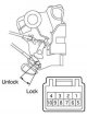
Checking the electric lock of the front door on the passenger side (double locking)
Check the operation of the passenger door lock electric drive in the positions indicated in the table. Connect the positive terminal of the battery to terminal "4" and the negative terminal to terminal "3", make sure...
Check the operation of the passenger door lock electric drive in the positions indicated in the table. Connect the positive terminal of the battery to terminal "4" and the negative terminal to terminal "3", make sure...
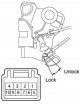
Checking the electric lock of the front door on the driver's side (double locking)
Check the operation of the driver's door lock electric drive in the positions indicated in the table. Connect the positive terminal of the battery to terminal "2" and the negative terminal to terminal "1", make sure...
Check the operation of the driver's door lock electric drive in the positions indicated in the table. Connect the positive terminal of the battery to terminal "2" and the negative terminal to terminal "1", make sure...
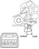
Checking the electric lock of the rear right door (double locking)
Check the operation of the rear right door lock electric drive in the positions indicated in the table. Connect the positive terminal of the battery to terminal "2" and the negative terminal to terminal "1", make sure...
Check the operation of the rear right door lock electric drive in the positions indicated in the table. Connect the positive terminal of the battery to terminal "2" and the negative terminal to terminal "1", make sure...

Checking the electric lock of the rear left door (double locking)
Check the operation of the rear left door lock electric drive in the positions indicated in the table. Connect the positive terminal of the battery to terminal "4" and the negative terminal to terminal "3", make sure...
Check the operation of the rear left door lock electric drive in the positions indicated in the table. Connect the positive terminal of the battery to terminal "4" and the negative terminal to terminal "3", make sure...

Checking the main window switch
Check for continuity between the terminals of the main power window switch. Fig. 7.69. Power window master switch connector If there is no continuity, replace the main switch. The glass is closed The glass is open
Check for continuity between the terminals of the main power window switch. Fig. 7.69. Power window master switch connector If there is no continuity, replace the main switch. The glass is closed The glass is open
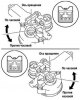
Checking the window lift motors
Check the operation of the right front door window lift motor. Connect terminal "5" of the electric motor connector to the positive terminal of the battery, and terminal "4" to the negative terminal. Make sure the motor...
Check the operation of the right front door window lift motor. Connect terminal "5" of the electric motor connector to the positive terminal of the battery, and terminal "4" to the negative terminal. Make sure the motor...

Checking the main power window relay
Check for continuity between the relay terminals when voltage is applied. Fig. 7.71. Main power relay connector If the results do not match those shown in the table, replace the relay. Standard check
Check for continuity between the relay terminals when voltage is applied. Fig. 7.71. Main power relay connector If the results do not match those shown in the table, replace the relay. Standard check

Checking the front seat adjustment switch
Check for continuity between the terminals of the front seat adjustment switch connector. Fig. 7.72. Front seat adjustment switch connector If the results do not match those shown in the table, replace the switch....
Check for continuity between the terminals of the front seat adjustment switch connector. Fig. 7.72. Front seat adjustment switch connector If the results do not match those shown in the table, replace the switch....

Checking the seat adjustment motors
Connect the battery to the terminals of the electric motor connector, check by changing the polarity of the voltage that the anchor rotates in both directions. Fig. 7.73. Seat adjustment electric motor test diagram If...
Connect the battery to the terminals of the electric motor connector, check by changing the polarity of the voltage that the anchor rotates in both directions. Fig. 7.73. Seat adjustment electric motor test diagram If...
Checking thermal fuses
Connect the positive terminal of the battery to terminal "1", the positive wire of the ammeter to terminal "2", and the negative wire of the ammeter to the negative terminal of the battery. Turn on the motor being...
Connect the positive terminal of the battery to terminal "1", the positive wire of the ammeter to terminal "2", and the negative wire of the ammeter to the negative terminal of the battery. Turn on the motor being...

Checking the washer motor
Pour the fluid into the washer reservoir. Connect the positive terminal of the battery to terminal "2", the positive wire of the ammeter to terminal "1", and the negative wire of the ammeter to the negative terminal of...
Pour the fluid into the washer reservoir. Connect the positive terminal of the battery to terminal "2", the positive wire of the ammeter to terminal "1", and the negative wire of the ammeter to the negative terminal of...
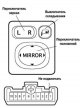
Checking the conductivity of the mirror position adjustment switch
Fig. 7.75. Mirror position adjustment switch connector Disconnect the switch connector and check the continuity between the terminals using the tables. Left mirror Right mirror Folding mirrors
Fig. 7.75. Mirror position adjustment switch connector Disconnect the switch connector and check the continuity between the terminals using the tables. Left mirror Right mirror Folding mirrors
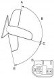
Checking the electric motor for folding mirrors
Connect the battery to the terminals of the electric motor connector, check the signal by changing the position of the mirror according to the data in the table. Fig. 7.76. Schematic diagram for checking the operability...
Connect the battery to the terminals of the electric motor connector, check the signal by changing the position of the mirror according to the data in the table. Fig. 7.76. Schematic diagram for checking the operability...

Checking the rear window defroster relay
Check for continuous continuity between terminals "1" and "2" of the heater relay. Fig. 7.77. Rear window defroster relay connector Check for continuity between terminals "1" and "2" of the relay when applying battery...
Check for continuous continuity between terminals "1" and "2" of the heater relay. Fig. 7.77. Rear window defroster relay connector Check for continuity between terminals "1" and "2" of the relay when applying battery...
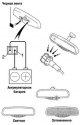
Checking the interior rearview mirror
Connect the positive battery terminal to terminal "1" and the negative battery terminal to terminal "2". Fig. 7.78. Interior rearview mirror test diagram Cover with black tape (see fig. 7.78) interior rearview mirror...
Connect the positive battery terminal to terminal "1" and the negative battery terminal to terminal "2". Fig. 7.78. Interior rearview mirror test diagram Cover with black tape (see fig. 7.78) interior rearview mirror...

Fuses and relays — location and ratings
Fig. 7.79. Location of relay and fuse boxes The location of the relay and fuse blocks is shown in Fig. 7.79. Fig. 7.80. Numbering of relays and fuses of the engine room junction block The numbering of the relays and...
Fig. 7.79. Location of relay and fuse boxes The location of the relay and fuse blocks is shown in Fig. 7.79. Fig. 7.80. Numbering of relays and fuses of the engine room junction block The numbering of the relays and...
This section is available on: russian, bulgarian, belarusian, ukrainian, serbian, croatian, romanian, polish, slovak, hungarian
Similar sections for other Toyota models
➥ Equipment and devices Toyota Dyna Y50/Y60 (1984-1995)
➥ Equipment and devices Toyota Highlander 1 (2000-2007, petrol)
➥ Equipment and devices Toyota 4Runner N120 (1989-1995)
➥ Equipment and devices Toyota Corona T190 (1992-1997)
➥ Equipment and devices Toyota Corolla E80 (1983-1990)
➥ Equipment and devices Toyota RAV 4 XA20 (2000-2005)
Link in different formats to this article
TEXTHTMLBB Code
- User manual
- Vehicle description
- Keys, locks and alarms
- Governing bodies
- Salon equipment
- Driving and operation
- Maintenance
- Power unit
- 4-cylinder engine
- Control system (I4)
- Engine overhaul (I4)
- 6-cylinder engine
- Control system (V6)
- Engine overhaul (V6)
- Transmission
- Clutch
- Mechanical gearbox
- Automatic gearbox
- Drive mechanism
- Chassis, running gear
- Wheels and tires
- Car suspension
- Steering
- Brake system
- Body and interior
- Exterior (external elements)
- Doors, locks and windows
- Air conditioning and heater
- Electrical equipment
- Equipment and devices
- Power devices
- Electrical circuits
- General information
- Controls and instruments
- Driving and operation
- Daily care
- Maintenance
- Power unit
- 4-cylinder engine
- 6-cylinder engine
- Engine overhaul
- Engine electrical equipment
- Cooling system
- Heating and ventilation
- Fuel system
- Exhaust system
- Transmission
- Mechanical gearbox
- Automatic gearbox
- Clutch
- Chassis, running gear
- Suspension and axle shafts
- Steering
- Brake system
- Body and interior
- Exterior (external elements)
- Interior (internal elements)
- Doors, locks and windows
- Electrical equipment
- Equipment and devices
- Electrical circuits
- General information
- User manual
- Maintenance
- Power unit
- 4-cylinder engine
- 6-cylinder engine
- Overhaul of engines
- Cooling and heating
- Fuel system
- Engine electrical equipment
- Control system
- Transmission
- Mechanical gearbox
- Automatic gearbox
- Clutch and drive shafts
- Chassis, running gear
- Brake system
- Car suspension
- Steering
- Body and interior
- Exterior (external elements)
- Interior (internal elements)
- Doors, locks and windows
- Electrical equipment
- Equipment and devices
- Headlights and lighting
- Electrical circuits
- General information
- User manual
- Maintenance
- Power unit
- Petrol engines
- Diesel engines
- Engine overhaul
- Cooling and lubrication system
- Fuel system (diesel)
- Fuel injection (petrol)
- Engine electrical equipment
- Transmission
- Clutch and cardan
- Automatic gearbox
- Chassis, running gear
- Front suspension
- Rear suspension
- Steering
- Brake system
- Body and interior
- Body elements
- Air conditioning and heater
- SRS security system
- Electrical equipment
- Equipment and devices
- Electrical circuits