



Share information:
Car automatic transmission Toyota Vista 4 (V40)

General description of automatic transmission
Note: - The automatic transmission type is stamped on an aluminum plate located in the engine compartment, in the line designated TRANS/AXLE. - Operation of the automatic transmission, replacement of fluids in the...
Note: - The automatic transmission type is stamped on an aluminum plate located in the engine compartment, in the line designated TRANS/AXLE. - Operation of the automatic transmission, replacement of fluids in the...

Preliminary checks
Checking and adjusting the automatic transmission control rod 1. When switching the selector from the "N" position to other positions, check that the selector moves smoothly and the indicator correctly indicates the...
Checking and adjusting the automatic transmission control rod 1. When switching the selector from the "N" position to other positions, check that the selector moves smoothly and the indicator correctly indicates the...
Automatic transmission diagnostics
Note: Malfunctions occurring in the gearbox may be related to either the engine, or the control system, or the gearbox itself. Therefore, before starting the check, it is necessary to determine the area of their...
Note: Malfunctions occurring in the gearbox may be related to either the engine, or the control system, or the gearbox itself. Therefore, before starting the check, it is necessary to determine the area of their...

Self-diagnosis system (A140E, A540N)
General information 1. The self-diagnosis function is built into the electronic control unit of the automatic transmission. Using the overdrive mode off indicator, the system can warn the driver about a malfunction in...
General information 1. The self-diagnosis function is built into the electronic control unit of the automatic transmission. Using the overdrive mode off indicator, the system can warn the driver about a malfunction in...

Troubleshooting automatic transmission
Note (A540H): In case of simultaneous failure of two speed sensors (front and rear output shafts of the gearbox) the fault code will not appear and the self-diagnosis system will not work. However, in the selector...
Note (A540H): In case of simultaneous failure of two speed sensors (front and rear output shafts of the gearbox) the fault code will not appear and the self-diagnosis system will not work. However, in the selector...

Checking the electrical components of the control system
1. Check the voltage at the terminals of the automatic transmission control unit connector. a) Remove the center panel. b) Turn on the ignition. c) Measure the voltage at each terminal of the automatic transmission and...
1. Check the voltage at the terminals of the automatic transmission control unit connector. a) Remove the center panel. b) Turn on the ignition. c) Measure the voltage at each terminal of the automatic transmission and...
Test on a fully braked car (stall test)
This test checks the performance of the gearbox and engine by measuring the rotation speed at maximum load in the "D" and "R" ranges. Note: The test should be carried out at the operating temperature of the automatic...
This test checks the performance of the gearbox and engine by measuring the rotation speed at maximum load in the "D" and "R" ranges. Note: The test should be carried out at the operating temperature of the automatic...
Checking the gear engagement time
If you move the selector to the "D" or "R" position with the engine idling, some time should pass before you feel a slight jolt. The length of this delay can be used to judge the serviceability of the forward clutch,...
If you move the selector to the "D" or "R" position with the engine idling, some time should pass before you feel a slight jolt. The length of this delay can be used to judge the serviceability of the forward clutch,...

Hydraulic test
Checking the pressure in the main line 1. Preparation: a) Warm up the transmission fluid to operating temperature (50 - 80°C). b) Unscrew the plug and connect a pressure gauge in its place. Important: Always check the...
Checking the pressure in the main line 1. Preparation: a) Warm up the transmission fluid to operating temperature (50 - 80°C). b) Unscrew the plug and connect a pressure gauge in its place. Important: Always check the...

Test of the interaxle differential lock clutch (A540N)
1. Preparation: a) Warm up the automatic transmission fluid to operating temperature (50-80°C). b) Unscrew the service plug of the gearbox housing and connect a pressure gauge in its place. Caution: Perform the check in...
1. Preparation: a) Warm up the automatic transmission fluid to operating temperature (50-80°C). b) Unscrew the service plug of the gearbox housing and connect a pressure gauge in its place. Caution: Perform the check in...

Road test
Note: Before starting the test, warm up the automatic transmission fluid to a temperature of 50-80°C. Test on "D" range Move the selector to the "D" range and press the accelerator pedal all the way down. 1. Check for...
Note: Before starting the test, warm up the automatic transmission fluid to a temperature of 50-80°C. Test on "D" range Move the selector to the "D" range and press the accelerator pedal all the way down. 1. Check for...

Selector and ignition key locking system
Checking the selector lock 1. Turn the ignition key to the "ON" position. 2. Move the selector to position "P" and release the selector lock. 3. Make sure that the selector is locked in this position. 4. While holding...
Checking the selector lock 1. Turn the ignition key to the "ON" position. 2. Move the selector to position "P" and release the selector lock. 3. Make sure that the selector is locked in this position. 4. While holding...

Replacing drive shaft seals
Removal 1. Remove the left and right drive shafts (see chapter " Front Drive Shafts - Removal "). 4. Remove the left and right drive shaft seals using a puller. Installation 1. Install the left drive shaft oil seal. a)...
Removal 1. Remove the left and right drive shafts (see chapter " Front Drive Shafts - Removal "). 4. Remove the left and right drive shaft seals using a puller. Installation 1. Install the left drive shaft oil seal. a)...
Replacing the propeller shaft seal (A540N)
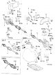
1. Drain the oil from the transfer case. 2. Remove the driveshaft. 3. Using a puller, remove the propeller shaft seal. Drive shafts. 1 - side protective cover No.1, 2 - steering rod end, 3 - support, 4 - bracket, 5 -...
1. Drain the oil from the transfer case. 2. Remove the driveshaft. 3. Using a puller, remove the propeller shaft seal. Drive shafts. 1 - side protective cover No.1, 2 - steering rod end, 3 - support, 4 - bracket, 5 -...

Engine start inhibit switch
Removal Note: Install in the reverse order of removal. After installation, perform a road test. 1. Remove the starter inhibit switch lever. a) Unscrew the nut and remove the automatic transmission control rod....
Removal Note: Install in the reverse order of removal. After installation, perform a road test. 1. Remove the starter inhibit switch lever. a) Unscrew the nut and remove the automatic transmission control rod....

Filter replacement
1. Unscrew the drain plug and drain the working fluid into a suitable container. Tightening torque during installation - 49 Nm 2. Unscrew the tray mounting bolts. Attention: Some amount of liquid always remains in the...
1. Unscrew the drain plug and drain the working fluid into a suitable container. Tightening torque during installation - 49 Nm 2. Unscrew the tray mounting bolts. Attention: Some amount of liquid always remains in the...

Throttle valve control cable
Removal Note: Install in the reverse order of removal. 1. Disconnect the throttle valve control cable. a) Disconnect the cable from the throttle sector. b) Disconnect the cable from the clamps on the engine....
Removal Note: Install in the reverse order of removal. 1. Disconnect the throttle valve control cable. a) Disconnect the cable from the throttle sector. b) Disconnect the cable from the clamps on the engine....
Gearbox assembly
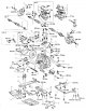
Note: remove and install as shown in the figure "Gearbox assembly" (see below). Gearbox assembly. 1 - cotter pin, 2 - nut stopper, 3 - speed sensor (ABS), 4, 5 - air filter assembly, 6, 8 - right drive shaft, 7 - cotter...
Note: remove and install as shown in the figure "Gearbox assembly" (see below). Gearbox assembly. 1 - cotter pin, 2 - nut stopper, 3 - speed sensor (ABS), 4, 5 - air filter assembly, 6, 8 - right drive shaft, 7 - cotter...

Checking the torque converter and torque converter drive plate
1. If the automatic transmission fluid is contaminated, flush the torque converter and the working fluid cooler. 2. Checking the freewheel clutch. a) Install the tool into the inner race of the freewheel clutch. b)...
1. If the automatic transmission fluid is contaminated, flush the torque converter and the working fluid cooler. 2. Checking the freewheel clutch. a) Install the tool into the inner race of the freewheel clutch. b)...

Transfer case (A540N)
Caution: To avoid damage to transmission components, partial loading is prohibited for 4WD models (by raising only one of the vehicle's axles). 4WD vehicles have permanent all-wheel drive, the so-called "Full time 4WD"...
Caution: To avoid damage to transmission components, partial loading is prohibited for 4WD models (by raising only one of the vehicle's axles). 4WD vehicles have permanent all-wheel drive, the so-called "Full time 4WD"...
This section is available on: russian, bulgarian, belarusian, ukrainian, serbian, croatian, romanian, polish, slovak, hungarian
Similar sections for other Toyota models
➥ Automatic gearbox Toyota Duet (1998-2004)
➥ Automatic gearbox Toyota Corona T190 (1992-1997)
➥ Automatic gearbox Toyota Cruiser 70 (1985-1996, diesel)
➥ Automatic gearbox Toyota Carina T190 (1992-1996)
➥ Automatic gearbox Toyota Corolla E80 (1983-1990)
➥ Automatic gearbox Toyota Highlander 1 (2000-2007, petrol)
Link in different formats to this article
TEXTHTMLBB Code
- User manual
- Vehicle description
- Keys, locks and alarms
- Governing bodies
- Salon equipment
- Driving and operation
- Maintenance
- Power unit
- 4-cylinder engine
- Control system (I4)
- Engine overhaul (I4)
- 6-cylinder engine
- Control system (V6)
- Engine overhaul (V6)
- Transmission
- Clutch
- Mechanical gearbox
- Automatic gearbox
- Drive mechanism
- Chassis, running gear
- Wheels and tires
- Car suspension
- Steering
- Brake system
- Body and interior
- Exterior (external elements)
- Doors, locks and windows
- Air conditioning and heater
- Electrical equipment
- Equipment and devices
- Power devices
- Electrical circuits
- General information
- Controls and instruments
- Driving and operation
- Daily care
- Maintenance
- Power unit
- 4-cylinder engine
- 6-cylinder engine
- Engine overhaul
- Engine electrical equipment
- Cooling system
- Heating and ventilation
- Fuel system
- Exhaust system
- Transmission
- Mechanical gearbox
- Automatic gearbox
- Clutch
- Chassis, running gear
- Suspension and axle shafts
- Steering
- Brake system
- Body and interior
- Exterior (external elements)
- Interior (internal elements)
- Doors, locks and windows
- Electrical equipment
- Equipment and devices
- Electrical circuits
- General information
- User manual
- Maintenance
- Power unit
- 4-cylinder engine
- 6-cylinder engine
- Overhaul of engines
- Cooling and heating
- Fuel system
- Engine electrical equipment
- Control system
- Transmission
- Mechanical gearbox
- Automatic gearbox
- Clutch and drive shafts
- Chassis, running gear
- Brake system
- Car suspension
- Steering
- Body and interior
- Exterior (external elements)
- Interior (internal elements)
- Doors, locks and windows
- Electrical equipment
- Equipment and devices
- Headlights and lighting
- Electrical circuits
- General information
- User manual
- Maintenance
- Power unit
- Petrol engines
- Diesel engines
- Engine overhaul
- Cooling and lubrication system
- Fuel system (diesel)
- Fuel injection (petrol)
- Engine electrical equipment
- Transmission
- Clutch and cardan
- Automatic gearbox
- Chassis, running gear
- Front suspension
- Rear suspension
- Steering
- Brake system
- Body and interior
- Body elements
- Air conditioning and heater
- SRS security system
- Electrical equipment
- Equipment and devices
- Electrical circuits