



Share information:
Brake system of the car Toyota Vista 4 (V40)
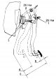
Checking and adjusting the brake pedal
1. Make sure the pedal height is adjusted as shown in the figure. Pedal height from floor covering - 187.5 - 197.5 mm 1 - brake light switch, 2 - rod lock nut, 3 - rod, 4 - pedal travel reserve, 5 - free pedal travel, 6...
1. Make sure the pedal height is adjusted as shown in the figure. Pedal height from floor covering - 187.5 - 197.5 mm 1 - brake light switch, 2 - rod lock nut, 3 - rod, 4 - pedal travel reserve, 5 - free pedal travel, 6...

Checking the performance of the vacuum booster
1. Checking the functionality. a) Press the brake pedal several times with the engine off and check that the pedal travel does not change. b) Press the brake pedal and start the engine. If the brake pedal goes down...
1. Checking the functionality. a) Press the brake pedal several times with the engine off and check that the pedal travel does not change. b) Press the brake pedal and start the engine. If the brake pedal goes down...

Bleeding the brake system
Note: After any work involving air entering the brake system, bleed it. Caution: Do not allow brake fluid to come into contact with painted surfaces. If brake fluid does come into contact with a painted surface, wash it...
Note: After any work involving air entering the brake system, bleed it. Caution: Do not allow brake fluid to come into contact with painted surfaces. If brake fluid does come into contact with a painted surface, wash it...

Checking and adjusting the parking brake
1. Remove the parking brake lever hole trim (parking brake pedal hole cover). 2. Check the stroke of the parking brake lever (pedal). Pull the lever (press the pedal) apply the parking brake all the way and count the...
1. Remove the parking brake lever hole trim (parking brake pedal hole cover). 2. Check the stroke of the parking brake lever (pedal). Pull the lever (press the pedal) apply the parking brake all the way and count the...

Master brake cylinder
Removal 1. Disconnect the low brake fluid level sensor connector. 2. Use a syringe to pump out the brake fluid from the reservoir. Caution: Do not allow brake fluid to come into contact with painted surfaces. If brake...
Removal 1. Disconnect the low brake fluid level sensor connector. 2. Use a syringe to pump out the brake fluid from the reservoir. Caution: Do not allow brake fluid to come into contact with painted surfaces. If brake...

Vacuum brake booster
Note: remove and install the brake booster using the assembly drawings. Checking the check valve 1. Remove the check valve and check that air flows from the vacuum receiver to the hose and does not flow in the opposite...
Note: remove and install the brake booster using the assembly drawings. Checking the check valve 1. Remove the check valve and check that air flows from the vacuum receiver to the hose and does not flow in the opposite...

Vacuum pump
Vacuum pump. 1 - vacuum pump, 2 - gasket. Examination 1. Connect the pressure gauge to the vacuum pump. 2. Turn on the engine. 3. Take pressure gauge readings with the engine idling. Idle speed - 750 - 850 rpm Vacuum -...
Vacuum pump. 1 - vacuum pump, 2 - gasket. Examination 1. Connect the pressure gauge to the vacuum pump. 2. Turn on the engine. 3. Take pressure gauge readings with the engine idling. Idle speed - 750 - 850 rpm Vacuum -...

Front brakes
Replacing brake pads 1. Remove the front wheel and temporarily secure the brake disc with wheel nuts. 2. Check the thickness of the brake pad linings through the inspection hole in the caliper. Minimum thickness - 1.0...
Replacing brake pads 1. Remove the front wheel and temporarily secure the brake disc with wheel nuts. 2. Check the thickness of the brake pad linings through the inspection hole in the caliper. Minimum thickness - 1.0...

Rear drum brakes
Removal 1. Remove the inspection hole plug and check the thickness of the brake shoe linings through it. Minimum thickness - 1.0 mm If the thickness of the linings is less than the minimum permissible, replace the brake...
Removal 1. Remove the inspection hole plug and check the thickness of the brake shoe linings through it. Minimum thickness - 1.0 mm If the thickness of the linings is less than the minimum permissible, replace the brake...

Rear disc brakes
Replacing brake pads 1. Remove the rear wheel and temporarily secure the brake disc with wheel nuts. 2. Check the thickness of the brake pad linings through the inspection hole in the caliper. Minimum thickness - 1.0 mm...
Replacing brake pads 1. Remove the rear wheel and temporarily secure the brake disc with wheel nuts. 2. Check the thickness of the brake pad linings through the inspection hole in the caliper. Minimum thickness - 1.0 mm...

Parking brake for rear disc brakes
Disassembling the parking brake 1. Remove the rear wheel. 2. Remove the rear caliper assembly. a) Unscrew the two mounting bolts and remove the rear caliper assembly. b) Hang the caliper so as not to stretch the hose....
Disassembling the parking brake 1. Remove the rear wheel. 2. Remove the rear caliper assembly. a) Unscrew the two mounting bolts and remove the rear caliper assembly. b) Hang the caliper so as not to stretch the hose....

Pressure regulator (P — valve)
Checking fluid pressure 1. Install the pressure gauges as shown in the figure. 1 - models with disc brakes, 2 - models with drum brakes. Removing the pressure regulator. 1 - air filter, 2 - coolant temperature switch, 3...
Checking fluid pressure 1. Install the pressure gauges as shown in the figure. 1 - models with disc brakes, 2 - models with drum brakes. Removing the pressure regulator. 1 - air filter, 2 - coolant temperature switch, 3...

Anti-lock braking system (ABS)
Description of the diagnostic system The electronic control unit has a fail-safe system that detects a system malfunction. When a malfunction is detected, the electronic control unit switches off the ABS system and the...
Description of the diagnostic system The electronic control unit has a fail-safe system that detects a system malfunction. When a malfunction is detected, the electronic control unit switches off the ABS system and the...

Control relay
Examination 1. (Models before 1996, models since 1996 (ZS-T)). Check the conductivity of the relay windings. a) Check for conductivity between terminals "5" and "6" of connector A. b) Check for conductivity between...
Examination 1. (Models before 1996, models since 1996 (ZS-T)). Check the conductivity of the relay windings. a) Check for conductivity between terminals "5" and "6" of connector A. b) Check for conductivity between...

Pressure modulator
Removal Note: Remove the modulator as shown in the figure "Pressure Modulator". Install in the reverse order of removal. After installation, bleed the brake system and check for leaks. Checking the parking brake sensor...
Removal Note: Remove the modulator as shown in the figure "Pressure Modulator". Install in the reverse order of removal. After installation, bleed the brake system and check for leaks. Checking the parking brake sensor...

Front wheel speed sensors
Removal Note: Installation is carried out in the reverse order of removal. 1. Disconnect the speed sensor connector. a) Remove the fender liner. b) Disconnect the connector. 2. Remove the speed sensor. a) Unscrew the...
Removal Note: Installation is carried out in the reverse order of removal. 1. Disconnect the speed sensor connector. a) Remove the fender liner. b) Disconnect the connector. 2. Remove the speed sensor. a) Unscrew the...

Rear wheel speed sensors
Removal and installation 1. Remove the seat cushion and backrest. 2. Disconnect the sensor connector. 3. Remove the sensor. a) Loosen the wiring harness mounting bolts. Tightening torque during installation - 5.5 Nm b)...
Removal and installation 1. Remove the seat cushion and backrest. 2. Disconnect the sensor connector. 3. Remove the sensor. a) Loosen the wiring harness mounting bolts. Tightening torque during installation - 5.5 Nm b)...

Checking the ABS circuit
1. Check the battery voltage with the ignition off. Nominal voltage - 10-14 V 2. With the ignition off, disconnect the ABS control unit connector and check the resistance and conductivity between the terminals of the...
1. Check the battery voltage with the ignition off. Nominal voltage - 10-14 V 2. With the ignition off, disconnect the ABS control unit connector and check the resistance and conductivity between the terminals of the...
This section is available on: russian, bulgarian, belarusian, ukrainian, serbian, croatian, romanian, polish, slovak, hungarian
Similar sections for other Toyota models
➥ Brake system Toyota 4Runner N120 (1989-1995)
➥ Brake system Toyota Highlander 1 (2000-2007, petrol)
➥ Brake system Toyota Cruiser 100 (1998-2007)
➥ Brake system Toyota Corona T190 (1992-1997)
➥ Brake system Toyota Corolla E80 (1983-1990)
➥ Brake system Toyota Duet (1998-2004)
Link in different formats to this article
TEXTHTMLBB Code
- User manual
- Vehicle description
- Keys, locks and alarms
- Governing bodies
- Salon equipment
- Driving and operation
- Maintenance
- Power unit
- 4-cylinder engine
- Control system (I4)
- Engine overhaul (I4)
- 6-cylinder engine
- Control system (V6)
- Engine overhaul (V6)
- Transmission
- Clutch
- Mechanical gearbox
- Automatic gearbox
- Drive mechanism
- Chassis, running gear
- Wheels and tires
- Car suspension
- Steering
- Brake system
- Body and interior
- Exterior (external elements)
- Doors, locks and windows
- Air conditioning and heater
- Electrical equipment
- Equipment and devices
- Power devices
- Electrical circuits
- General information
- Controls and instruments
- Driving and operation
- Daily care
- Maintenance
- Power unit
- 4-cylinder engine
- 6-cylinder engine
- Engine overhaul
- Engine electrical equipment
- Cooling system
- Heating and ventilation
- Fuel system
- Exhaust system
- Transmission
- Mechanical gearbox
- Automatic gearbox
- Clutch
- Chassis, running gear
- Suspension and axle shafts
- Steering
- Brake system
- Body and interior
- Exterior (external elements)
- Interior (internal elements)
- Doors, locks and windows
- Electrical equipment
- Equipment and devices
- Electrical circuits
- General information
- User manual
- Maintenance
- Power unit
- 4-cylinder engine
- 6-cylinder engine
- Overhaul of engines
- Cooling and heating
- Fuel system
- Engine electrical equipment
- Control system
- Transmission
- Mechanical gearbox
- Automatic gearbox
- Clutch and drive shafts
- Chassis, running gear
- Brake system
- Car suspension
- Steering
- Body and interior
- Exterior (external elements)
- Interior (internal elements)
- Doors, locks and windows
- Electrical equipment
- Equipment and devices
- Headlights and lighting
- Electrical circuits
- General information
- User manual
- Maintenance
- Power unit
- Petrol engines
- Diesel engines
- Engine overhaul
- Cooling and lubrication system
- Fuel system (diesel)
- Fuel injection (petrol)
- Engine electrical equipment
- Transmission
- Clutch and cardan
- Automatic gearbox
- Chassis, running gear
- Front suspension
- Rear suspension
- Steering
- Brake system
- Body and interior
- Body elements
- Air conditioning and heater
- SRS security system
- Electrical equipment
- Equipment and devices
- Electrical circuits