



Share information:
Vehicle fuel system Toyota Camry 1 (XV10)

Fuel system specifications
Fuel pressure Ignition on, engine not running 2.5 – 3.0 bar At idle speed: - vacuum hose removed 2.5 – 3.0 bar - vacuum hose installed 2.0 – 2.5 bar Residual pressure in the fuel system 1.4 bar Fuel injector resistance...
Fuel pressure Ignition on, engine not running 2.5 – 3.0 bar At idle speed: - vacuum hose removed 2.5 – 3.0 bar - vacuum hose installed 2.0 – 2.5 bar Residual pressure in the fuel system 1.4 bar Fuel injector resistance...
General information about the fuel system
Caution! The fuel system remains under pressure for a long time after the engine has been switched off. Whenever the fuel lines are disconnected, the pressure in the fuel system must first be relieved. The fuel system...
Caution! The fuel system remains under pressure for a long time after the engine has been switched off. Whenever the fuel lines are disconnected, the pressure in the fuel system must first be relieved. The fuel system...

Relieving pressure in the fuel system
Electrical diagram of the fuel pump power supply 1. Remove the fuel filler cap. 2. Remove the AM2 30 amp fuel pump fuse from the main fuse box (see fig. Electrical diagram of fuel pump power supply). 3. Run the engine...
Electrical diagram of the fuel pump power supply 1. Remove the fuel filler cap. 2. Remove the AM2 30 amp fuel pump fuse from the main fuse box (see fig. Electrical diagram of fuel pump power supply). 3. Run the engine...

Checking the performance of the fuel pump
1. Turn on the ignition, but do not start the engine. 2. Connect contacts +B and Fp with an additional wire on the control connector (see Fig. Electrical diagram of the fuel pump power supply ). On models with a 1MZ-FE...
1. Turn on the ignition, but do not start the engine. 2. Connect contacts +B and Fp with an additional wire on the control connector (see Fig. Electrical diagram of the fuel pump power supply ). On models with a 1MZ-FE...

Checking the pressure generated by the fuel pump
Supplying battery voltage with additional wires to check the functionality of the fuel pump on models with 1MZ-FE V6 engines since 1994. Adapters used to connect the pressure gauge to the top of the fuel filter The...
Supplying battery voltage with additional wires to check the functionality of the fuel pump on models with 1MZ-FE V6 engines since 1994. Adapters used to connect the pressure gauge to the top of the fuel filter The...
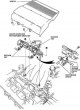
Checking the fuel pressure regulator
Location of the vacuum changeover valve (VSV) on the engine 1. Disconnect the vacuum hose from the fuel pressure regulator and connect a hand vacuum pump with a pressure gauge in its place. Start the engine and measure...
Location of the vacuum changeover valve (VSV) on the engine 1. Disconnect the vacuum hose from the fuel pressure regulator and connect a hand vacuum pump with a pressure gauge in its place. Start the engine and measure...

Checking the fuel pump relay
Location of electrical components and sensors of the engine fuel system Location of the circuit breaker relay There are two relays in the fuel pump control circuit - the EFI main relay and the open circuit relay. 1....
Location of electrical components and sensors of the engine fuel system Location of the circuit breaker relay There are two relays in the fuel pump control circuit - the EFI main relay and the open circuit relay. 1....

Fuel pump — removal and installation
1. Remove the fuel filler cap. 2. Remove the ground cable from the battery. Warning: If your radio has an anti-theft code, make sure you have the connection codes before disconnecting the battery. Caution! On models...
1. Remove the fuel filler cap. 2. Remove the ground cable from the battery. Warning: If your radio has an anti-theft code, make sure you have the connection codes before disconnecting the battery. Caution! On models...

Fuel level sensor — checking and replacement
Examination 1. Fill the tank full of fuel. 2. Remove the rear seat and fuel tank cover. 3. Disconnect the electrical connector from the fuel tank. 4. Using an ohmmeter, check the resistance between pins 1 and 2 of the...
Examination 1. Fill the tank full of fuel. 2. Remove the rear seat and fuel tank cover. 3. Disconnect the electrical connector from the fuel tank. 4. Using an ohmmeter, check the resistance between pins 1 and 2 of the...
Fuel tank — removal and installation
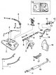
Fuel tank 1 – fastening belt; 2 – fuel tank; 3 – EVAP fuel pipe; 4 – pressure fuel line; 5 – branch pipe; 6 – gasket; 7 – gasket; 8 – fuel hose; 9 – installation mark; 10 – bracket; 11 – fuel filler neck; 12 – lid; 13 –...
Fuel tank 1 – fastening belt; 2 – fuel tank; 3 – EVAP fuel pipe; 4 – pressure fuel line; 5 – branch pipe; 6 – gasket; 7 – gasket; 8 – fuel hose; 9 – installation mark; 10 – bracket; 11 – fuel filler neck; 12 – lid; 13 –...

Air filter — removal and installation
1. Release the clips and remove the air cleaner housing and filter element. 2. Loosen the clamps and remove the air intake hose. 3. Remove the three bolts and remove the air filter housing from the engine compartment....
1. Release the clips and remove the air cleaner housing and filter element. 2. Loosen the clamps and remove the air intake hose. 3. Remove the three bolts and remove the air filter housing from the engine compartment....

Accelerator cable — removal, installation and adjustment
Removal 1. Remove the ground cable from the battery. Warning: If your radio has an anti-theft code, make sure you have the connection codes before disconnecting the battery. Caution! On models from 1993 onwards, the...
Removal 1. Remove the ground cable from the battery. Warning: If your radio has an anti-theft code, make sure you have the connection codes before disconnecting the battery. Caution! On models from 1993 onwards, the...
Electronic fuel injection system EFL
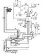
Electronic fuel injection system EFL four-cylinder engine 1 – additional oxygen sensor; 2 – main oxygen sensor; 3 – fuel injector; 4 – fuel pressure regulator; 5 – fuel pulsation damper; 6 – fuel filter; 7 – fuel pump;...
Electronic fuel injection system EFL four-cylinder engine 1 – additional oxygen sensor; 2 – main oxygen sensor; 3 – fuel injector; 4 – fuel pressure regulator; 5 – fuel pulsation damper; 6 – fuel filter; 7 – fuel pump;...
Fuel injection system — design description
An electric fuel pump located inside the fuel tank delivers fuel under constant pressure to the fuel rail, which distributes it to the fuel injectors. The fuel injectors spray fuel near the intake valves. The amount of...
An electric fuel pump located inside the fuel tank delivers fuel under constant pressure to the fuel rail, which distributes it to the fuel injectors. The fuel injectors spray fuel near the intake valves. The amount of...

Checking the fuel injection system
Possible carbon deposits inside the throttle body If a fault has occurred in the fuel system, first check that all electrical connectors are securely connected and protected from corrosion. Also check the cleanliness of...
Possible carbon deposits inside the throttle body If a fault has occurred in the fuel system, first check that all electrical connectors are securely connected and protected from corrosion. Also check the cleanliness of...

Throttle Body — Checking and Replacing
Examination Checking the vacuum in the throttle body vacuum hoses of a four-cylinder engine Checking the vacuum in the throttle body vacuum hoses of a six-cylinder engine 1. Check that the accelerator cable moves...
Examination Checking the vacuum in the throttle body vacuum hoses of a four-cylinder engine Checking the vacuum in the throttle body vacuum hoses of a six-cylinder engine 1. Check that the accelerator cable moves...

Throttle Position Sensor (TPS) — Checking and Replacing
Examination Checking the resistance between the corresponding terminals of the throttle position sensor on four-cylinder engines Checking the resistance between the corresponding terminals of the throttle position...
Examination Checking the resistance between the corresponding terminals of the throttle position sensor on four-cylinder engines Checking the resistance between the corresponding terminals of the throttle position...

Fuel Pressure Regulator — Replacement
Position of the O-ring when installing the pressure regulator on the fuel line 1. Relieve pressure in the fuel line. 2. Remove the ground cable from the battery. Warning: If your radio has an anti-theft code, make sure...
Position of the O-ring when installing the pressure regulator on the fuel line 1. Relieve pressure in the fuel line. 2. Remove the ground cable from the battery. Warning: If your radio has an anti-theft code, make sure...

Cold start injector for 3VZ-FE engine
Examination 1. Disconnect the electrical connector from the cold start fuel injector. 2. Using an ohmmeter, check the resistance between the cold start fuel injector terminals. 3. Connect the electrical connector to the...
Examination 1. Disconnect the electrical connector from the cold start fuel injector. 2. Using an ohmmeter, check the resistance between the cold start fuel injector terminals. 3. Connect the electrical connector to the...
Cold Start Injector Time Relay 3VZ-FE
Examination The time relay is located next to the coolant temperature sensor. 1. Disconnect the electrical connector from the cold start injector timer relay and, using an ohmmeter, check the resistance between the...
Examination The time relay is located next to the coolant temperature sensor. 1. Disconnect the electrical connector from the cold start injector timer relay and, using an ohmmeter, check the resistance between the...

Air Control Valve (IAC) — Checking and Replacing
Examination Connecting the tachometer to the IG terminal of the data link connector located in the lower part of the engine compartment Checking the resistance between the electrical connector terminals of the control...
Examination Connecting the tachometer to the IG terminal of the data link connector located in the lower part of the engine compartment Checking the resistance between the electrical connector terminals of the control...

Fuel line and fuel injectors — replacement
Location of the screws for fastening the changeover vacuum valve 1. Relieve pressure in the fuel system. 2. Remove the ground cable from the battery. Warning: If your radio has an anti-theft code, make sure you have the...
Location of the screws for fastening the changeover vacuum valve 1. Relieve pressure in the fuel system. 2. Remove the ground cable from the battery. Warning: If your radio has an anti-theft code, make sure you have the...

Air conditioning system idle mode valve
Examination 1. Apply the parking brake and place the gearshift lever in neutral. Connect the tachometer according to the manufacturer's instructions. Connect the wire from the tachometer to the IG terminal of the...
Examination 1. Apply the parking brake and place the gearshift lever in neutral. Connect the tachometer according to the manufacturer's instructions. Connect the wire from the tachometer to the IG terminal of the...
Air intake chamber (V6 engines only)
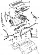
V6 Engine Air Intake Chamber 1 – fuel line; 2 – left fuel line; 3 – gasket; 4 – bracket; 5 – air intake chamber bracket; 6 – casing; 7 – control valves; 8 – air intake chamber; 9 – air duct; 10 – gaskets; 11 – right...
V6 Engine Air Intake Chamber 1 – fuel line; 2 – left fuel line; 3 – gasket; 4 – bracket; 5 – air intake chamber bracket; 6 – casing; 7 – control valves; 8 – air intake chamber; 9 – air duct; 10 – gaskets; 11 – right...
This section is available on: russian, bulgarian, belarusian, ukrainian, serbian, croatian, romanian, polish, slovak, hungarian
Similar sections for other Toyota models
➥ Fuel system Toyota 4Runner N120 (1989-1995)
➥ Power and exhaust systems Toyota Cruiser 100 (1998-2007)
➥ Fuel system Toyota Corolla Verso 3 (2004-2009)
➥ Fuel system Toyota Carina T190 (1992-1996)
➥ Fuel system (diesel) Toyota RAV 4 XA20 (2000-2005)
➥ Supply and exhaust system Toyota Highlander 1 (2000-2007, petrol)
Link in different formats to this article
TEXTHTMLBB Code
- User manual
- Vehicle description
- Keys, locks and alarms
- Governing bodies
- Salon equipment
- Driving and operation
- Maintenance
- Power unit
- 4-cylinder engine
- Control system (I4)
- Engine overhaul (I4)
- 6-cylinder engine
- Control system (V6)
- Engine overhaul (V6)
- Transmission
- Clutch
- Mechanical gearbox
- Automatic gearbox
- Drive mechanism
- Chassis, running gear
- Wheels and tires
- Car suspension
- Steering
- Brake system
- Body and interior
- Exterior (external elements)
- Doors, locks and windows
- Air conditioning and heater
- Electrical equipment
- Equipment and devices
- Power devices
- Electrical circuits
- General information
- Controls and instruments
- Driving and operation
- Daily care
- Maintenance
- Power unit
- 4-cylinder engine
- 6-cylinder engine
- Engine overhaul
- Engine electrical equipment
- Cooling system
- Heating and ventilation
- Fuel system
- Exhaust system
- Transmission
- Mechanical gearbox
- Automatic gearbox
- Clutch
- Chassis, running gear
- Suspension and axle shafts
- Steering
- Brake system
- Body and interior
- Exterior (external elements)
- Interior (internal elements)
- Doors, locks and windows
- Electrical equipment
- Equipment and devices
- Electrical circuits
- General information
- User manual
- Maintenance
- Power unit
- 4-cylinder engine
- 6-cylinder engine
- Overhaul of engines
- Cooling and heating
- Fuel system
- Engine electrical equipment
- Control system
- Transmission
- Mechanical gearbox
- Automatic gearbox
- Clutch and drive shafts
- Chassis, running gear
- Brake system
- Car suspension
- Steering
- Body and interior
- Exterior (external elements)
- Interior (internal elements)
- Doors, locks and windows
- Electrical equipment
- Equipment and devices
- Headlights and lighting
- Electrical circuits
- General information
- User manual
- Maintenance
- Power unit
- Petrol engines
- Diesel engines
- Engine overhaul
- Cooling and lubrication system
- Fuel system (diesel)
- Fuel injection (petrol)
- Engine electrical equipment
- Transmission
- Clutch and cardan
- Automatic gearbox
- Chassis, running gear
- Front suspension
- Rear suspension
- Steering
- Brake system
- Body and interior
- Body elements
- Air conditioning and heater
- SRS security system
- Electrical equipment
- Equipment and devices
- Electrical circuits