



Share information:
Vehicle fuel system Toyota Camry 2 (XV20)

Fuel injection system components
Fuel Injection System Components - 4-Cylinder Engines 1. Control system wire connector; 2. Fuel line; 3. Intake manifold; 4. Throttle; 5. Idle speed control valve Fuel injection system components – 6-cylinder engines 1....
Fuel Injection System Components - 4-Cylinder Engines 1. Control system wire connector; 2. Fuel line; 3. Intake manifold; 4. Throttle; 5. Idle speed control valve Fuel injection system components – 6-cylinder engines 1....

Fuel system specifications
Fuel system pressure 44 – 50 psi Residual pressure in the system after 5 minutes 21 psi minimum Injector resistance (approximately) 13.4 – 14.2 Ohm Tightening torques, Nm Throttle valve nuts 14 Fuel line bolts:...
Fuel system pressure 44 – 50 psi Residual pressure in the system after 5 minutes 21 psi minimum Injector resistance (approximately) 13.4 – 14.2 Ohm Tightening torques, Nm Throttle valve nuts 14 Fuel line bolts:...

Relieving pressure in the fuel system
1. Remove the rear seat and carpet to access the fuel pump cover. Disconnect the wire. 2. Start the engine and wait until it stalls. Disconnect the negative battery cable. 3. Loosen the fuel line connection at the rear...
1. Remove the rear seat and carpet to access the fuel pump cover. Disconnect the wire. 2. Start the engine and wait until it stalls. Disconnect the negative battery cable. 3. Loosen the fuel line connection at the rear...

Fuel pump and fuel pressure
Fuel pump electrical circuit 1. Main relay of the fuel system EPI; 2. Fuel pump relay (circuit breaker); 3. Fuel pump; 4. Ignition switch; 5. Parking and neutral position switch; 6. Starter relay; 7. Starter; 8. Battery...
Fuel pump electrical circuit 1. Main relay of the fuel system EPI; 2. Fuel pump relay (circuit breaker); 3. Fuel pump; 4. Ignition switch; 5. Parking and neutral position switch; 6. Starter relay; 7. Starter; 8. Battery...

Fuel Lines and Line Joints — Repair and Replacement
Before starting work, be sure to release the pressure in the fuel system. The fuel supply and return lines run from the fuel tank to the engine compartment and are clamped to the underbody. Check the lines for damage....
Before starting work, be sure to release the pressure in the fuel system. The fuel supply and return lines run from the fuel tank to the engine compartment and are clamped to the underbody. Check the lines for damage....
Removal and installation the fuel pump
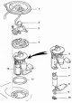
Fuel pump - type A 1. Lid; 2. Fuel pump and sensor wire; 3. Protective cover; 4. Plate; 5. Fuel hose; 6. Connector; 7. Fuel pump; 8. Fuel pump filter; 9. Clamp; 10. Rubber gasket; 11. Gasket; 12. Fuel pump assembly Fuel...
Fuel pump - type A 1. Lid; 2. Fuel pump and sensor wire; 3. Protective cover; 4. Plate; 5. Fuel hose; 6. Connector; 7. Fuel pump; 8. Fuel pump filter; 9. Clamp; 10. Rubber gasket; 11. Gasket; 12. Fuel pump assembly Fuel...

Fuel pressure regulator — removal and installation
Removal 1. Release the pressure in the system. Disconnect the negative battery cable. 2. Remove the fuel pump unit. Unscrew the fuel filter screw (indicated by the arrow). 3. Remove the fuel filter. 4. Unscrew the...
Removal 1. Release the pressure in the system. Disconnect the negative battery cable. 2. Remove the fuel pump unit. Unscrew the fuel filter screw (indicated by the arrow). 3. Remove the fuel filter. 4. Unscrew the...

Fuel Level Gauge Sensor — Checking and Replacing
Examination 1. Release the pressure in the system. Disconnect the negative battery cable. 2. Remove the fuel pump unit. 3. Disconnect the sensor wire and connect an ohmmeter to pins 2 and 3. Measure the resistance of...
Examination 1. Release the pressure in the system. Disconnect the negative battery cable. 2. Remove the fuel pump unit. 3. Disconnect the sensor wire and connect an ohmmeter to pins 2 and 3. Measure the resistance of...

Fuel tank — removal and installation
Fuel tank 0. Casing; 1. Filler cap; 2. Gasket; 3. Fuel tank filler pipe; 4. Protective pipe cover; 5. Tank mounts; 6. Fuel tank; 7. Fuel tank filler hose; 8. Fuel vapor recovery system hose; 9. Gasket; 10. Fuel pipe;...
Fuel tank 0. Casing; 1. Filler cap; 2. Gasket; 3. Fuel tank filler pipe; 4. Protective pipe cover; 5. Tank mounts; 6. Fuel tank; 7. Fuel tank filler hose; 8. Fuel vapor recovery system hose; 9. Gasket; 10. Fuel pipe;...

Air Filter Housing — Removal and Installation
Removal 1. Disconnect the clips, remove the filter cover and take out the filter element. 2. Disconnect the air intake duct from the cover. 3. Remove the three bolts and remove the filter housing. Installation...
Removal 1. Disconnect the clips, remove the filter cover and take out the filter element. 2. Disconnect the air intake duct from the cover. 3. Remove the three bolts and remove the filter housing. Installation...

Accelerator cable — removal and installation
Removal 1. Disconnect the negative battery cable. 2. Loosen the cable locknut. 3. Turn the throttle lever and disconnect the cable from the lever. 4. Disconnect the cable from the accelerator pedal. Installation...
Removal 1. Disconnect the negative battery cable. 2. Loosen the cable locknut. 3. Turn the throttle lever and disconnect the cable from the lever. 4. Disconnect the cable from the accelerator pedal. Installation...

Electronic Fuel Injection System — Check
The pulse multi-point fuel injection system includes three subsystems: the air intake system (air filter, air intake ducts, air flow sensor, throttle, idle air control system and intake manifold), electronic control...
The pulse multi-point fuel injection system includes three subsystems: the air intake system (air filter, air intake ducts, air flow sensor, throttle, idle air control system and intake manifold), electronic control...

Throttle — Checking and Replacing
Four-cylinder engines 1. Vacuum hoses; 2. Gasket; 3. Fuel vapor recovery system hose; 4. Throttle body housing; 5. Throttle position sensor wire; 6. Wire; 7. Pipe connecting the throttle to the air filter; 8. Coolant...
Four-cylinder engines 1. Vacuum hoses; 2. Gasket; 3. Fuel vapor recovery system hose; 4. Throttle body housing; 5. Throttle position sensor wire; 6. Wire; 7. Pipe connecting the throttle to the air filter; 8. Coolant...

Fuel line and injectors — removal and installation
Removal 1. Disconnect the negative battery cable. 2. Release the pressure in the fuel system. 3. In six-cylinder engines, remove two bolts (indicated by arrows in the figure on the left) and move the vacuum valve...
Removal 1. Disconnect the negative battery cable. 2. Release the pressure in the fuel system. 3. In six-cylinder engines, remove two bolts (indicated by arrows in the figure on the left) and move the vacuum valve...
This section is available on: russian, bulgarian, belarusian, ukrainian, serbian, croatian, romanian, polish, slovak, hungarian
Similar sections for other Toyota models
➥ Fuel system Toyota 4Runner N120 (1989-1995)
➥ Power and exhaust systems Toyota Cruiser 100 (1998-2007)
➥ Fuel system (petrol) Toyota RAV 4 XA20 (2000-2005)
➥ Fuel system Toyota Corolla Verso 3 (2004-2009)
➥ Fuel system Toyota Carina T190 (1992-1996)
➥ Supply and exhaust system Toyota Highlander 1 (2000-2007, petrol)
Link in different formats to this article
TEXTHTMLBB Code
- User manual
- Vehicle description
- Keys, locks and alarms
- Governing bodies
- Salon equipment
- Driving and operation
- Maintenance
- Power unit
- 4-cylinder engine
- Control system (I4)
- Engine overhaul (I4)
- 6-cylinder engine
- Control system (V6)
- Engine overhaul (V6)
- Transmission
- Clutch
- Mechanical gearbox
- Automatic gearbox
- Drive mechanism
- Chassis, running gear
- Wheels and tires
- Car suspension
- Steering
- Brake system
- Body and interior
- Exterior (external elements)
- Doors, locks and windows
- Air conditioning and heater
- Electrical equipment
- Equipment and devices
- Power devices
- Electrical circuits
- General information
- Controls and instruments
- Driving and operation
- Daily care
- Maintenance
- Power unit
- 4-cylinder engine
- 6-cylinder engine
- Engine overhaul
- Engine electrical equipment
- Cooling system
- Heating and ventilation
- Fuel system
- Exhaust system
- Transmission
- Mechanical gearbox
- Automatic gearbox
- Clutch
- Chassis, running gear
- Suspension and axle shafts
- Steering
- Brake system
- Body and interior
- Exterior (external elements)
- Interior (internal elements)
- Doors, locks and windows
- Electrical equipment
- Equipment and devices
- Electrical circuits
- General information
- User manual
- Maintenance
- Power unit
- 4-cylinder engine
- 6-cylinder engine
- Overhaul of engines
- Cooling and heating
- Fuel system
- Engine electrical equipment
- Control system
- Transmission
- Mechanical gearbox
- Automatic gearbox
- Clutch and drive shafts
- Chassis, running gear
- Brake system
- Car suspension
- Steering
- Body and interior
- Exterior (external elements)
- Interior (internal elements)
- Doors, locks and windows
- Electrical equipment
- Equipment and devices
- Headlights and lighting
- Electrical circuits
- General information
- User manual
- Maintenance
- Power unit
- Petrol engines
- Diesel engines
- Engine overhaul
- Cooling and lubrication system
- Fuel system (diesel)
- Fuel injection (petrol)
- Engine electrical equipment
- Transmission
- Clutch and cardan
- Automatic gearbox
- Chassis, running gear
- Front suspension
- Rear suspension
- Steering
- Brake system
- Body and interior
- Body elements
- Air conditioning and heater
- SRS security system
- Electrical equipment
- Equipment and devices
- Electrical circuits