



Share information:
Brake system of the car Toyota Camry 3 (XV30)
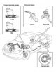
Brake system — general information
The vehicles described in this manual are equipped with a hydraulic brake system. The front brakes are disc brakes, the rear brakes are disc or drum brakes. All brakes are equipped with automatic adjustment of brake pad...
The vehicles described in this manual are equipped with a hydraulic brake system. The front brakes are disc brakes, the rear brakes are disc or drum brakes. All brakes are equipped with automatic adjustment of brake pad...

Vacuum brake booster
Fig. 6.3. Camry brake booster: 1 – brake hose No.3; 2 – brake hose No.2; 3 – brake hose No.5; 4 – brake hose No.4; 5 – master brake cylinder assembly; 6 – master cylinder reservoir (1MZ-FE); 7 – vacuum hose The vacuum...
Fig. 6.3. Camry brake booster: 1 – brake hose No.3; 2 – brake hose No.2; 3 – brake hose No.5; 4 – brake hose No.4; 5 – master brake cylinder assembly; 6 – master cylinder reservoir (1MZ-FE); 7 – vacuum hose The vacuum...

Anti-lock braking system (ABS)
Fig. 6.4. Diagram of the operation of the brake system circuit of the Camry car: 1 – front wheel speed sensors; 2 – brake fluid level indicator; 3 – brake light switch; 4 – master cylinder pressure sensor; 5 – master...
Fig. 6.4. Diagram of the operation of the brake system circuit of the Camry car: 1 – front wheel speed sensors; 2 – brake fluid level indicator; 3 – brake light switch; 4 – master cylinder pressure sensor; 5 – master...

Disc brakes on the front wheels
The brake caliper is attached to the steering knuckle with two bolts. The fluid pressure created by pressing the brake pedal is converted into braking force. This force acts equally on the piston and the caliper. As a...
The brake caliper is attached to the steering knuckle with two bolts. The fluid pressure created by pressing the brake pedal is converted into braking force. This force acts equally on the piston and the caliper. As a...

Checking and adjusting the brake system components
Check the brakes on a dry and level road. Check the brakes at various vehicle speeds with light and strong pressure on the brake pedal, avoiding locking the brakes and slipping the tires. There are three main factors...
Check the brakes on a dry and level road. Check the brakes at various vehicle speeds with light and strong pressure on the brake pedal, avoiding locking the brakes and slipping the tires. There are three main factors...
Checking the brake fluid level in the hydraulic reservoir
The brake fluid reservoir is located in the engine compartment. The reservoir has a transparent body, so the brake fluid level can be monitored from the outside. The brake fluid level should always be closer to the...
The brake fluid reservoir is located in the engine compartment. The reservoir has a transparent body, so the brake fluid level can be monitored from the outside. The brake fluid level should always be closer to the...
Brake hoses
Brake hoses should be checked at least twice a year. To prevent sudden failure of the brake system, carefully check the condition of all pipes and connections, paying particular attention to the following: Metal...
Brake hoses should be checked at least twice a year. To prevent sudden failure of the brake system, carefully check the condition of all pipes and connections, paying particular attention to the following: Metal...
Adjusting the brake pedal height
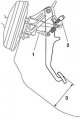
Fig. 6.8. Brake pedal height adjustment diagram: 1 – rod; 2 – brake light switch; 3 – pedal height Check and adjust the brake pedal height (Fig. 6.8). Pedal height from floor: 144.1–154.1 mm Disconnect the brake light...
Fig. 6.8. Brake pedal height adjustment diagram: 1 – rod; 2 – brake light switch; 3 – pedal height Check and adjust the brake pedal height (Fig. 6.8). Pedal height from floor: 144.1–154.1 mm Disconnect the brake light...

Checking the free travel of the brake pedal
Stop the engine and press the pedal several times to eliminate the vacuum in the vacuum booster. Fig. 6.10. Adjusting the brake pedal free travel Press the pedal until you feel resistance (Fig. 6.10). Pedal free play:...
Stop the engine and press the pedal several times to eliminate the vacuum in the vacuum booster. Fig. 6.10. Adjusting the brake pedal free travel Press the pedal until you feel resistance (Fig. 6.10). Pedal free play:...

Checking the brake pedal travel reserve
Fig. 6.11. Checking the brake pedal travel reserve Release the parking brake lever. With the engine running, press the pedal and measure the pedal travel (Fig. 6.11). Brake pedal travel from floor covering at 490 N...
Fig. 6.11. Checking the brake pedal travel reserve Release the parking brake lever. With the engine running, press the pedal and measure the pedal travel (Fig. 6.11). Brake pedal travel from floor covering at 490 N...

Checking the performance and tightness of the vacuum booster
Fig. 6.12. Checking the brake pedal travel with the engine off Press the brake pedal several times with the engine off and make sure that the pedal travel does not change (Fig. 6.12). Press the brake pedal and start the...
Fig. 6.12. Checking the brake pedal travel with the engine off Press the brake pedal several times with the engine off and make sure that the pedal travel does not change (Fig. 6.12). Press the brake pedal and start the...

Checking the vacuum booster valve
Remove the clamp and disconnect the vacuum hose. Remove the vacuum valve. Fig. 6.14. Checking the vacuum booster valve Blow out the valve and check if there is free air flow from the valve (Fig. 6.14). If there is no...
Remove the clamp and disconnect the vacuum hose. Remove the vacuum valve. Fig. 6.14. Checking the vacuum booster valve Blow out the valve and check if there is free air flow from the valve (Fig. 6.14). If there is no...

Bleeding the brake system
Fig. 6.15. Fill with fresh brake fluid Use only fresh DOT 3 or DOT 4 brake fluid. Bleeding the hydraulic drive of the service brake system is necessary to remove air, which significantly reduces braking efficiency. Air...
Fig. 6.15. Fill with fresh brake fluid Use only fresh DOT 3 or DOT 4 brake fluid. Bleeding the hydraulic drive of the service brake system is necessary to remove air, which significantly reduces braking efficiency. Air...

Bleeding the ABS/VSC pressure modulator
Also bleed the ABS/VSC system pressure modulator. Remove the modulator reservoir cap. Fig. 6.19. Attaching a special device to the pressure modulator for bleeding Attach the special device 09992-00242 instead. Connect...
Also bleed the ABS/VSC system pressure modulator. Remove the modulator reservoir cap. Fig. 6.19. Attaching a special device to the pressure modulator for bleeding Attach the special device 09992-00242 instead. Connect...

Checking and adjusting the parking brake
Check the travel of the parking brake lever. Pull the parking brake lever all the way down and count the number of clicks. Parking brake lever movement at 200 N force: 6–9 clicks Parking brake pedal movement at 300 N...
Check the travel of the parking brake lever. Pull the parking brake lever all the way down and count the number of clicks. Parking brake lever movement at 200 N force: 6–9 clicks Parking brake pedal movement at 300 N...

Removal the master brake cylinder
Caution! Do not allow brake fluid to come into contact with painted surfaces. If brake fluid does come into contact with a painted surface, wash it off immediately. Drain the brake fluid. Note: For models with 1MZ-FE...
Caution! Do not allow brake fluid to come into contact with painted surfaces. If brake fluid does come into contact with a painted surface, wash it off immediately. Drain the brake fluid. Note: For models with 1MZ-FE...

Disassembling the master brake cylinder
Using a screwdriver, push the pistons out to their full stroke, loosen the lock bolt and remove the O-ring. Note: Wrap the screwdriver with a bandage or adhesive tape to avoid damaging the pistons and cylinder bore....
Using a screwdriver, push the pistons out to their full stroke, loosen the lock bolt and remove the O-ring. Note: Wrap the screwdriver with a bandage or adhesive tape to avoid damaging the pistons and cylinder bore....
Checking and installing the master brake cylinder
Make sure there is no rust or scratches on the cylinder mirror. Check the cylinder for wear or damage. Replace the cylinder if necessary. Caution: Replace all parts included in the repair kit used to service the brake...
Make sure there is no rust or scratches on the cylinder mirror. Check the cylinder for wear or damage. Replace the cylinder if necessary. Caution: Replace all parts included in the repair kit used to service the brake...

Checking, removing and installing the brake booster
The brake booster, located on the firewall, operates using the vacuum in the intake manifold and atmospheric pressure. After completing each operation that involved removing any of the brake system components, perform a...
The brake booster, located on the firewall, operates using the vacuum in the intake manifold and atmospheric pressure. After completing each operation that involved removing any of the brake system components, perform a...

Replacing the front brake pads, removing, disassembling and installing the front caliper
When the cylinder body is open, do not press the brake pedal, otherwise the piston will jump out. Do not damage the piston dust boot and do not allow oil to get on the brake disc. When replacing the pads, always replace...
When the cylinder body is open, do not press the brake pedal, otherwise the piston will jump out. Do not damage the piston dust boot and do not allow oil to get on the brake disc. When replacing the pads, always replace...
Replacing rear brake pads, removing, disassembling and installing rear caliper
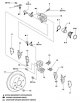
Fig. 6.47. Disc brake mechanisms of the rear wheels of the Camry: 1 – flexible hose; 2 – gasket; 3 – guide pin; 4 – anther; 5 – bleed nipple; 6 – protective cap of the bleed nipple; 7 – oil seal; 8 – piston; 9 – piston...
Fig. 6.47. Disc brake mechanisms of the rear wheels of the Camry: 1 – flexible hose; 2 – gasket; 3 – guide pin; 4 – anther; 5 – bleed nipple; 6 – protective cap of the bleed nipple; 7 – oil seal; 8 – piston; 9 – piston...

Disassembly, inspection and assembly of the parking brake mechanism
Disassemble the rear disc brake in the order described in the previous section. Hang the caliper without disassembling it and secure it securely with wire. Check that the brake hose is not stretched. Release the parking...
Disassemble the rear disc brake in the order described in the previous section. Hang the caliper without disassembling it and secure it securely with wire. Check that the brake hose is not stretched. Release the parking...

Removal and installation the front wheel speed sensor
Fig. 6.71. Front wheel speed sensor mountings To remove the front wheel speed sensor, remove the mudguard liner and disconnect the sensor connector and clamp as shown in Figure 6.71. Fig. 6.72. Releasing the speed...
Fig. 6.71. Front wheel speed sensor mountings To remove the front wheel speed sensor, remove the mudguard liner and disconnect the sensor connector and clamp as shown in Figure 6.71. Fig. 6.72. Releasing the speed...

Removal and installation the pressure modulator
Remove the right front fender liner. Loosen the air conditioner hose bracket mounting bolt. Fig. 6.74. Disconnecting the tubes from the pressure modulator Using a special tool, unscrew the 6 mounting nuts and disconnect...
Remove the right front fender liner. Loosen the air conditioner hose bracket mounting bolt. Fig. 6.74. Disconnecting the tubes from the pressure modulator Using a special tool, unscrew the 6 mounting nuts and disconnect...
Removal and installation the brake pedal
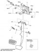
Fig. 6.76. Brake pedal components: 1 – brake light switch; 2 – pedal bracket; 3 – pedal mounting bushing seat; 4 – brake pedal; 5 – pedal stop; 6 – axle of the main brake cylinder fork; 7 – hairpin; 8 – return spring; 9...
Fig. 6.76. Brake pedal components: 1 – brake light switch; 2 – pedal bracket; 3 – pedal mounting bushing seat; 4 – brake pedal; 5 – pedal stop; 6 – axle of the main brake cylinder fork; 7 – hairpin; 8 – return spring; 9...
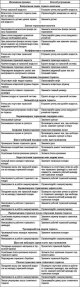
Possible malfunctions of the brake system
Table 6.1. Possible malfunctions of the brake system, their causes and methods of elimination
Table 6.1. Possible malfunctions of the brake system, their causes and methods of elimination
This section is available on: russian, bulgarian, belarusian, ukrainian, serbian, croatian, romanian, polish, slovak, hungarian
Similar sections for other Toyota models
➥ Brake system Toyota 4Runner N120 (1989-1995)
➥ Brake system Toyota Highlander 1 (2000-2007, petrol)
➥ Brake system Toyota Corona T190 (1992-1997)
➥ Brake system Toyota Corolla E80 (1983-1990)
➥ Brake system Toyota Cruiser 60/80 (1980-1997, petrol)
➥ Brake system Toyota Carina T190 (1992-1996)
Link in different formats to this article
TEXTHTMLBB Code
- User manual
- Vehicle description
- Keys, locks and alarms
- Governing bodies
- Salon equipment
- Driving and operation
- Maintenance
- Power unit
- 4-cylinder engine
- Control system (I4)
- Engine overhaul (I4)
- 6-cylinder engine
- Control system (V6)
- Engine overhaul (V6)
- Transmission
- Clutch
- Mechanical gearbox
- Automatic gearbox
- Drive mechanism
- Chassis, running gear
- Wheels and tires
- Car suspension
- Steering
- Brake system
- Body and interior
- Exterior (external elements)
- Doors, locks and windows
- Air conditioning and heater
- Electrical equipment
- Equipment and devices
- Power devices
- Electrical circuits
- General information
- Controls and instruments
- Driving and operation
- Daily care
- Maintenance
- Power unit
- 4-cylinder engine
- 6-cylinder engine
- Engine overhaul
- Engine electrical equipment
- Cooling system
- Heating and ventilation
- Fuel system
- Exhaust system
- Transmission
- Mechanical gearbox
- Automatic gearbox
- Clutch
- Chassis, running gear
- Suspension and axle shafts
- Steering
- Brake system
- Body and interior
- Exterior (external elements)
- Interior (internal elements)
- Doors, locks and windows
- Electrical equipment
- Equipment and devices
- Electrical circuits
- General information
- User manual
- Maintenance
- Power unit
- 4-cylinder engine
- 6-cylinder engine
- Overhaul of engines
- Cooling and heating
- Fuel system
- Engine electrical equipment
- Control system
- Transmission
- Mechanical gearbox
- Automatic gearbox
- Clutch and drive shafts
- Chassis, running gear
- Brake system
- Car suspension
- Steering
- Body and interior
- Exterior (external elements)
- Interior (internal elements)
- Doors, locks and windows
- Electrical equipment
- Equipment and devices
- Headlights and lighting
- Electrical circuits
- General information
- User manual
- Maintenance
- Power unit
- Petrol engines
- Diesel engines
- Engine overhaul
- Cooling and lubrication system
- Fuel system (diesel)
- Fuel injection (petrol)
- Engine electrical equipment
- Transmission
- Clutch and cardan
- Automatic gearbox
- Chassis, running gear
- Front suspension
- Rear suspension
- Steering
- Brake system
- Body and interior
- Body elements
- Air conditioning and heater
- SRS security system
- Electrical equipment
- Equipment and devices
- Electrical circuits