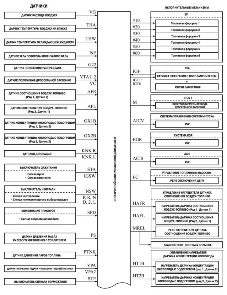
Pic. 2.204. Configuration diagram of the 1MZ-FE engine management system of the new Camry (part 1)
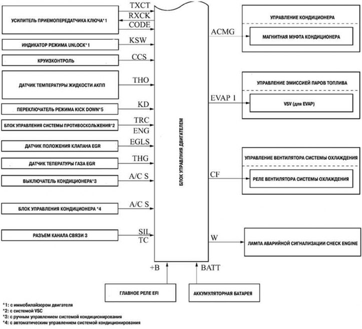
Pic. 2.204b. Configuration diagram of the 1MZ-FE engine management system of the new Camry (part 2)
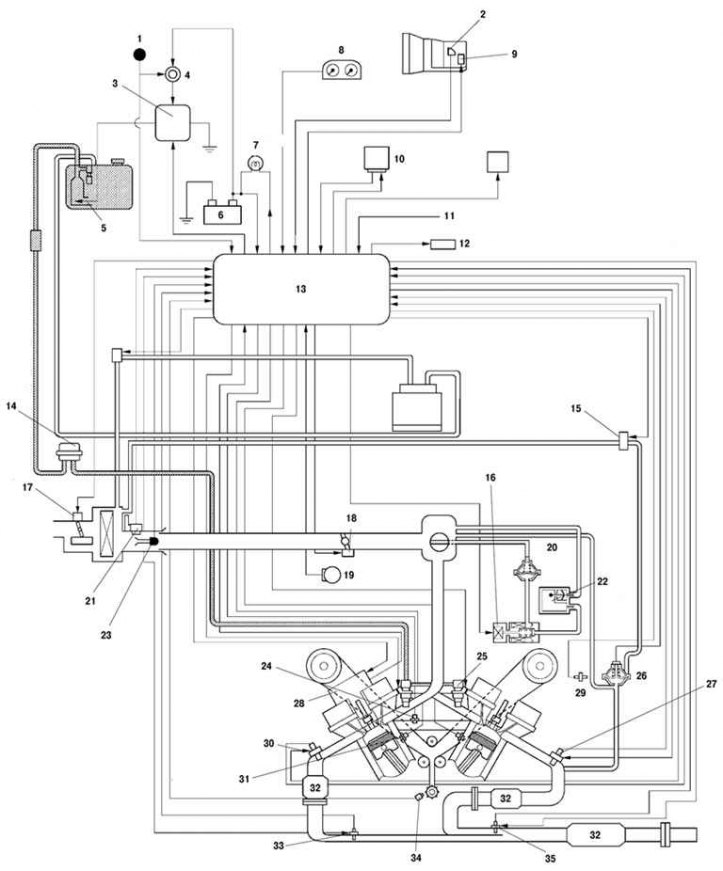
Pic. 2.205. Diagram of the 1MZ-FE engine management system of the new Camry: 1 - ignition switch; 2 - neutral switch; 3 - circuit disconnect relay; 4 - the main relay EFI; 5 - fuel pump; 6 - storage battery; 7 - alarm lamp
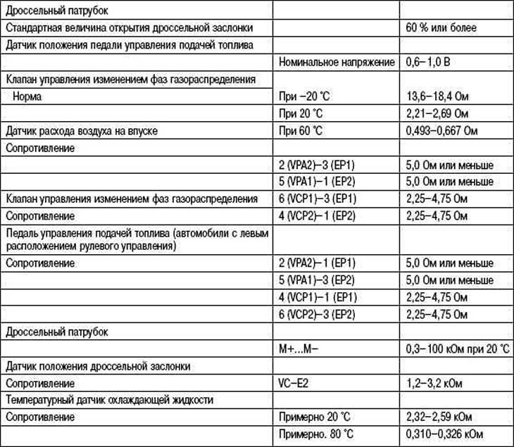
The structure of the 1MZ-FE engine control system is shown in Table 2.25.
On fig. 2.204. and 2.204b shows the configuration diagram of the 1MZ-FE engine management system of the new Camry. Data for the maintenance of such a system are given in Table 2.26.
Table 2.25. The structure of the engine control system 1MZ-FE
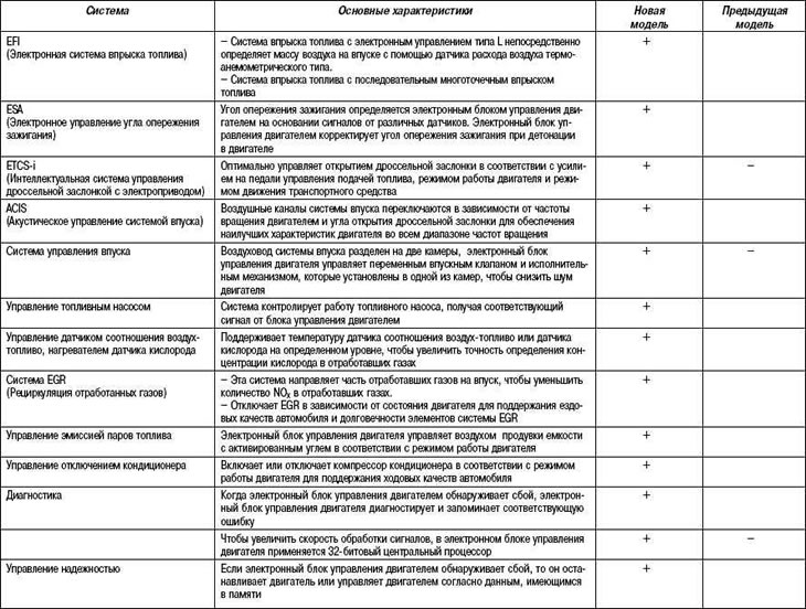
Table 2.26. Data for servicing the engine management system 1MZ-FE