
Installation of the block of manometers
1. Attach charging hoses to gauge block. Tighten the nuts by hand.
2. Close the safety valves on the charging hoses.
3. Close the gauge block valves.
4. Remove the plugs from the cooling line service valves.
5. Connect charging hoses to service valves. Make sure the high and low pressure hoses are connected to the appropriate service valves.
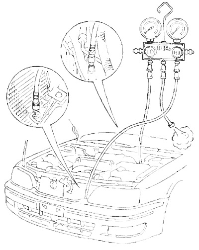
6. Open the safety valves on the charging hoses.
Removing the gauge block
1. Close the gauge block valves.
2. Close the safety valves on the charging hoses.
2. Disconnect the charge hoses from the cooling line service valves.
3. Install plugs on service valves.
Relay test
1. Checking the main heater relay.
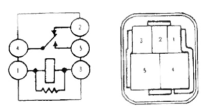
A) Check for continuity between terminals "1" And "3".
b) Check for continuity between terminals "2" And "6".
V) Check for continuity between terminals "4" And "2" relay when battery voltage is applied to the terminals "1" And "3".
2. Checking fan relay #2.
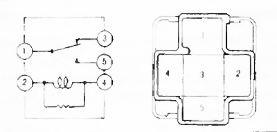
A) Check for continuity between terminals "2" And "4".
b) Check for continuity between terminals "1" And "3".
V) Check for continuity between terminals "1" And "6" relay when battery voltage is applied to the terminals "2" And "4".
3. Checking fan relay #3.
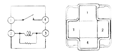
A) Check continuity between terminals 2" And "3".
b) Check for continuity between terminals "1" And "4".
V) Check for continuity between terminals "1" And "4" relay when battery voltage is applied to the terminals "2" And "3".
4. Checking the EX-HI relay.
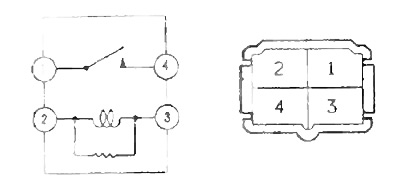
A) Check for continuity between terminals "2" And "3".
b) Check for continuity between terminals "1" And "4".
V) Check for continuity between terminals "1" And "4" relay when battery voltage is applied to the terminals "2" And "3".
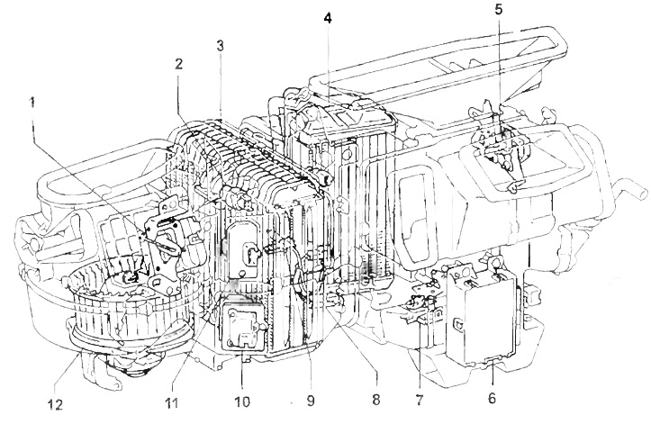
Cooling unit and heater.
1 - air intake damper servo drive,
2 - EX-HI relay,
3 - evaporator,
4 - heater radiator,
5 - airflow direction damper servo drive,
6 - air conditioning amplifier,
7 - air mixing damper servo drive,
8 - coolant temperature sensor,
9 - temperature sensor behind the evaporator,
10 - power transistor,
11 - heater fan resistor,
12 - heater fan motor.
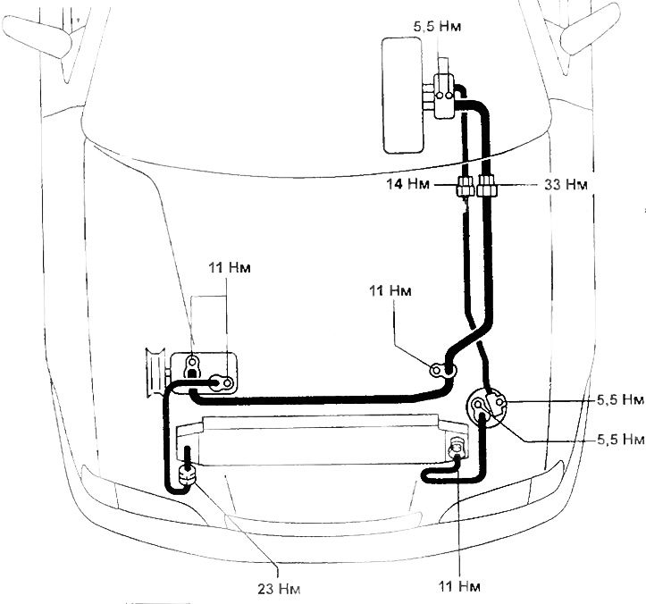
Tightening torques for threaded connections of the air conditioning system.
5. Checking the electromagnetic clutch relay.
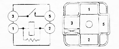
A) Check for continuity between terminals "1" And "2".
b) Check for continuity between terminals "3" And "6".
V) Check for continuity between terminals "3" And "6" relay when battery voltage is applied to the terminals "1" And "2".