



Type 1
1. Checking the heater fan switch.
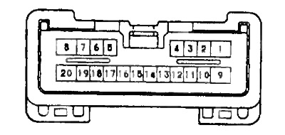
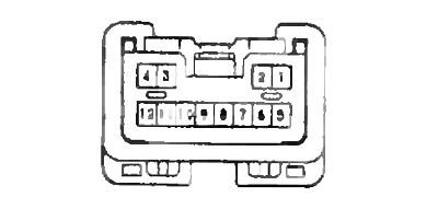
a) Measure the voltage at terminals "10" and "12" of the connector at different switch positions.
Normal voltage:
- OFF — 1.8-2.2 V
- LO — 2.8-3.2 V
- MID — 3.8-4.2 V
- HI — 4.8-5.2 V
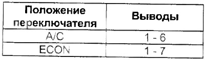
2. Checking the air conditioner switch and the "ECON" switch.
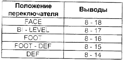
3. Checking the blower direction switch.
(The original publication can be found on the website: «ToyotaMan»)
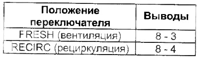
4. Checking the switch "FRESH/RECIRC".
5. Checking the temperature controller.
a) Measure the resistance between terminals "11" and "12" when moving the regulator from the maximum cooling position to the maximum heating position.
Normal resistance:
- max cooling - 0 Ohm
- max heating - about 3 kOhm
b) Check the smoothness of the resistance change.
6. Checking the rear window defroster switch.
a) Connect the battery to terminals "1" (+) and "8" (-).
b) Connect (+) of the battery via a 12V 3.4W 12V 3.4W test lamp, from (+) to terminal "2". When you press the switch, the lamp should light for 12-18 minutes.
7. Checking the indicators and backlight. Checking the indicators.
a) Connect the battery to the terminals "1" (+), "8" and "5" (-).
b) When each switch is pressed, its lamp should light up.
Note: The rear window defroster lamp stays on for 12-18 minutes.
Checking the backlight.
The same connection, when connected to terminal "9" (+) of the battery, the backlight lamp lights up.
Type 2
1. Checking the backlight.
Connect the battery to the terminals "6" (+), "8" (-). The backlight should be on.
Checking the heater fan motor
1. Connect the battery to terminals "1" (+) and "2" (-) of the connector, check the smooth rotation of the rotor.
2. Measure the motor current.
- Nominal current - less than 3 A
Capacitor motor
1. Connect the battery to terminals "2" (+) and "1" (-) of the connector, check the smooth rotation of the rotor.
2. Measure the motor current.
- Nominal current - less than 1.5 A
Checking servos
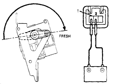
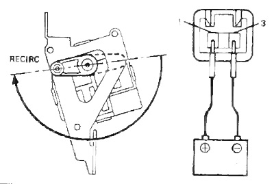
1. Checking the air intake flap servo drive.
a) Connect the "+" of the battery to terminal "1", to terminal "2", check that the valve moves to the "FRESH" position (ventilation).
b) Connect the "+" of the battery to terminal "1", "-" to terminal "3", check that the valve moves to the "RECIRC" position (recirculation).
2. Checking the servo drive of the flow mixing valve.
a) Connect the battery to terminals "1" (+) and "2" (-) of the connector. Check that the lever moves smoothly from the "COOL" to "HOT" position.
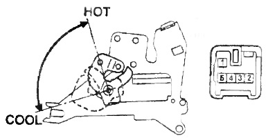
b) Change the polarity of the voltage, check that the lever moves to the "COOL" position.
c) Measure the resistance between terminals "5" and "4".
- Resistance - 4.8-7.2 kOhm
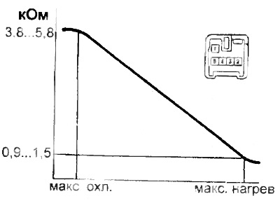
d) Check that when the damper is moved from the "COOL" to "HOT" position, the resistance between terminals "4" and "3" changes as shown in the figure.
3. Checking the air flow direction flap servo drive
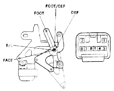
a) Connect the battery to terminals "2" (+) and "1" (-) of the connector
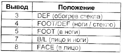
b) By connecting each connector lead to the negative battery terminal, check that the lever moves to the position shown in the table.
 |  |