



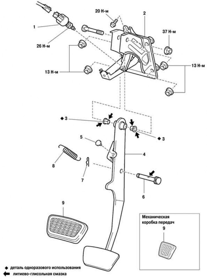
Fig. 6.76. Brake pedal components: 1 – brake light switch; 2 – pedal bracket; 3 – pedal mounting bushing seat; 4 – brake pedal; 5 – pedal stop; 6 – axle of the main brake cylinder fork; 7 – hairpin; 8 – return spring; 9 – overlay
The brake pedal components are shown in Figure 6.76.
Removal
Remove the lower section of the instrument panel from the driver's side.
Unscrew the brake light switch from the brake pedal assembly.
Remove the cotter pin and fork axle from the brake booster clevis.
Remove the brake pedal assembly mounting nuts. Pull the brake booster toward the engine compartment. Do not deform the brake pipe.
Remove the brake booster link from the push rod.
Remove the steering column from the steering gear beam.
Examination
Check the brake pedal. Make sure there is no deformation of the clevis pin, cracks in the welding areas, cracks or deformation in the clevis pin stop.
Installation
Installation is performed in the reverse order of removal.
After installing the pedal, adjust it.