
This force is transmitted through the tie rods and tie rod ends to the steering knuckles, which turn the front wheels. If the hydraulic booster malfunctions, the vehicle is driven in the normal mode. However, this requires more effort. The rotational movement of the steering wheel is transmitted to the gear. As the gear rotates, the gear teeth engage with the rack teeth, thereby causing the rack to move.
Disconnect the terminals from the battery.
Set the steering wheel straight.
Using socket wrench (Torx), unscrew the 2 bolts securing the side plugs with an Allen socket.
Remove the plugs.
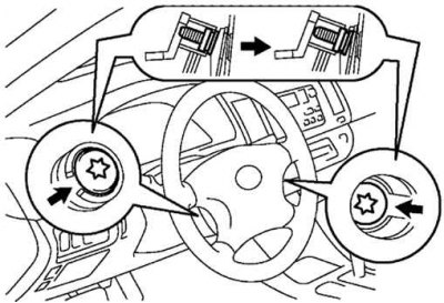
Pic. 5.17. Loosening the steering wheel pad mounting bolts
Loosen the steering wheel pad mounting bolts. Loosen the bolts until they are fixed as shown in figure 5.17.
Take out an overlay of a steering wheel.
Attention! Do not pull the pad sharply. Be careful not to break the steering airbag wire connectors.
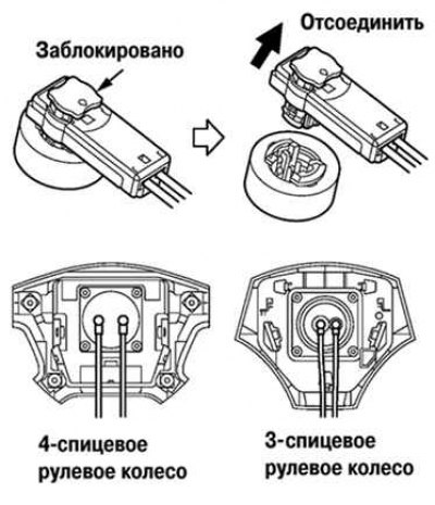
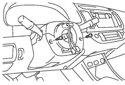
Pic. 5.18. Airbag wire connectors
Using a screwdriver, disconnect the 2 steering airbag wire connectors as shown in Figure 5.18.
Remove the steering wheel cover.
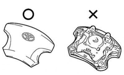
Pic. 5.19. Steering wheel pad content rule
Attention! Keep the pad face up at all times to avoid damage (pic. 5.19). Do not attempt to remove the steering airbag capsule.
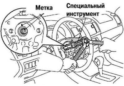
Pic. 5.20. Removing the steering wheel
Mark the steering wheel and main shaft. Using the special tool, remove the steering wheel nut and remove the steering wheel (pic. 5.20).
Pic. 5.21. Bolts of fastening of the top casing of a steering column
Using a screwdriver, unscrew the 2 screws securing the upper casing of the steering column (pic. 5.21).
After unscrewing the three bolts, remove the cover of the lower casing No. 2.
With the connector disconnected, remove the headlight dimmer assembly.
Remove the coiled wire combination switch.
With the connector disconnected, remove the wiper switch assembly.
Note. Do not disassemble the coiled wire and avoid getting oil on it.
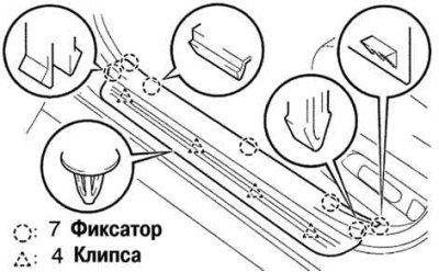
Pic. 5.22. Fastening of finishing of a threshold of a forward door
Remove the front door sill trim by removing the 7 clips and 4 fastening clips (pic. 5.22).
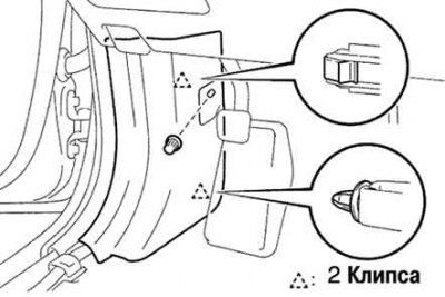
Pic. 5.23. Fastening of a lateral decorative slip of salon
Disconnect the 2 clips and remove the side trim of the passenger compartment (pic. 5.23).
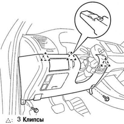
Pic. 5.24. Fastening the lower trim panel on the driver's side
Turn away two bolts, disconnect a cable of the lock of a cowl. Disconnect the three fastening clips and remove the lower trim panel from the driver's side (pic. 5.24).
Loosen the four screws and remove the bottom trim panel insert.
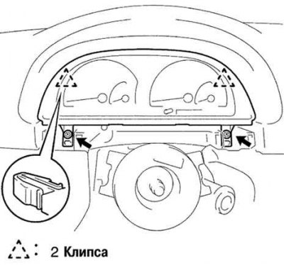
Pic. 5.25. Instrument cluster trim fixture
Unscrew the two screws, disconnect the 2 fastening clips and remove the trim of the instrument cluster (pic. 5.25)
Remove the ignition lock trim.