
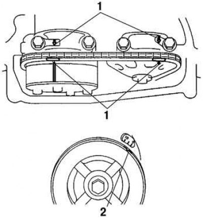
Pic. 2.173. Combination of markings with marks on the camshaft bearing caps: 1 - marks on the covers; 2 - marking «0»
Turn the crankshaft pulley and align it with the mark «0» on the timing chain cover. Make sure the marks on the sprockets are aligned with the marks on the #1 and #2 camshaft bearing caps.
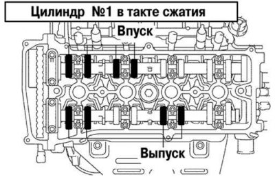
Pic. 2.174. The procedure for measuring the clearance of the valve actuator of cylinder No. 1 of the compression stroke
Measure a backlash in a drive of the valves shown in drawing 2.174.
Using a feeler gauge, measure the clearance between the tappet and the camshaft cam. Make a note of any clearance that is outside the specified limits. These values will be used later to select the required pusher size.
Standard valve clearance (on a cold engine):
- intake - 0.19–0.29 mm;
- graduation - 0.30–0.40 mm.
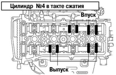
Pic. 2.175. The procedure for measuring the clearance of the valve actuator of cylinder No. 4 of the compression stroke
Rotate the crankshaft one revolution (360°) and line up the labels. Check up backlashes in a drive of the valves shown in drawing 2.175, having repeated the above procedure.