Main relay of the fuel injection system
1. Remove the main relay of the injection system.
2. Check the resistance of the relay winding.
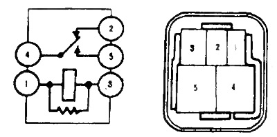
A) Use an ohmmeter to check for continuity between the terminals "1" And "3" (resistance - 50-90 Ohm). Resistance between terminals "2" And "4" - 0 ohm.
b) Then use an ohmmeter to verify that there is no continuity between the terminals "4" And "5" (resistance - infinity).
3. Check relay operation.
A) Apply battery voltage to terminals "1" And "3" relay connector.
b) Use an ohmmeter to check for continuity between the terminals "2" And "4".
b) Use an ohmmeter to check for continuity between the terminals "4" And "5".
If the conditions in points 1 and 2 are not met, replace the relay.
4. If necessary, the relay housing can be removed and, before throwing it away, try to eliminate the cause of the failure. To do this, clean all contacts, and check the resistance of the windings in two directions, since there may be diodes that shunt the windings. If there are no identical diodes in the winding resistance in both directions, then you can connect the battery in any sequence. If not, then connect the battery with the correct polarity.
5. Reinstall the relay.
Electric fan relay
1. Disconnect the negative plug from the storage battery.
2. Remove the electric fan relay.
3. Check the electric fan relay.
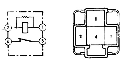
Check for continuity between terminals "1" And "2" (50 - 8C Ohm) "3" And "4" (0 ohm).
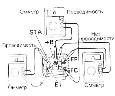
Fuel pump relay switch
Type 1
1. Remove the fuel pump relay switch.
2. Check the electrical circuit of the relay using an ohmmeter.
A) Check for continuity between the terminals: "STA" And "E1", "+V" and TS".
b) Check for continuity between terminals "+V" And "FP".
If these conditions are not met, replace the relay.
3. Check relay operation.
A) Apply voltage from the battery to the terminals '"STA" And "EG * and using an ohmmeter, check for continuity between the terminals "+V" And "FP".
b) Apply battery voltage to terminals "+V" And "FC" and using an ohmmeter, check for continuity between the terminals "+V" And "FP".
If the relay does not operate as described, replace the relay.
4. Install the relay.
Type 2
1. Remove the fuel pump relay switch
2. Check the electrical circuit of the relay using an ohmmeter.
A) Check the resistance between the terminals: "ST" And "EG, "IG" And "FC", "IN" And "FC".
Resistance between pins:
- "ST" And "E1" — 20-30 Ohm
- "IG" u "FС" - 110-170 Ohm
- "IN" And "FС" - infinity
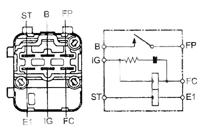
b) Apply battery voltage to terminals "ST" And "E1", and use an ohmmeter to check for continuity between the terminals "+V" And "FP".
If the relay does not operate as described, replace the relay.
Manifold absolute pressure sensor
1. Check the supply voltage of the intake manifold absolute pressure sensor
A) Disconnect the absolute pressure sensor connector.
b) Turn on the ignition.
Using a voltmeter, measure the voltage between the terminals "VC" And "E1" absolute pressure sensor connector.
- Rated voltage - 4.5-5.5 V
2. Check the output signal of the absolute pressure sensor.
A) Turn on the ignition.
b) Disconnect the vacuum hose from the intake manifold.
V) Connect a voltmeter to the terminals "PIM" And "E2" connector of the electronic control unit and measure the output signal voltage at atmospheric pressure.
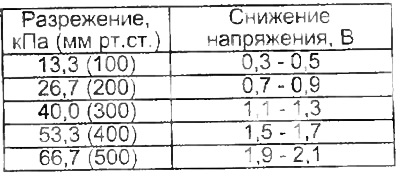
G) Apply vacuum to the sensor in steps ranging from 13.3 kPa (100 mmHg) up to 66.7 kPa (500 mmHg).
d) Measure the voltage drop for each vacuum value.
Coolant temperature sensor and intake air temperature sensor
Checking the coolant temperature sensor
1. To remove the coolant temperature sensor, drain the coolant.
2. Remove the sensor, disconnect the connector.
3. Using an ohmmeter, measure the resistance of the sensor.
4. According to the graph, find the value of the resistance of the sensor (temperature dependent) and compare with the measurement results.
If the resistance value is outside the tolerance shown in the graph, replace the sensor.
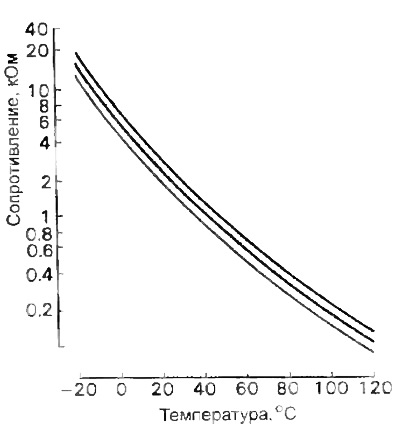
Characteristics of the coolant temperature sensor
5. Reinstall the sensor.
6. Fill with coolant (Removed coolant temperature sensor).
Knock sensor
Checking the knock sensor
1. Disconnect (-) wire from the negative battery terminal.
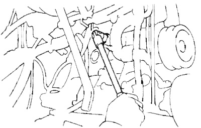
2. Remove the knock sensor by first disconnecting its connector.
3. Use an ohmmeter to verify that there is no continuity between the sensor terminal and the case. Otherwise, replace the sensor.
4. Install the knock sensor back and connect its connector.
- Tightening torque - 44 Nm
5. Connect (-) wire to the negative battery terminal.
Otherwise, replace the valve.
Idle speed electropneumatic valve
Note: Valve configuration may differ from what is shown.
1. Remove the valve.
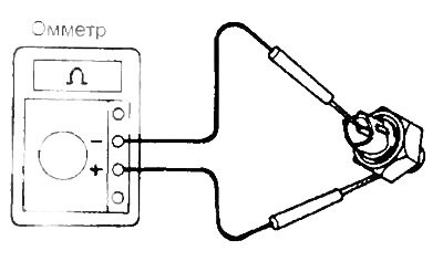
2. Check valve for open circuit.
Using an ohmmeter, verify that there is no open circuit in the valve winding by measuring its electrical resistance.
- Valve winding resistance value (cold) is - 4 ohms
Otherwise, replace the valve.
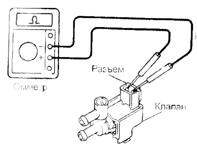
3. Using an ohmmeter, one wire of which is connected in turn to the terminals of the valve connector, and the other to the valve body, make sure that the valve winding is not shorted to the body ("mass").
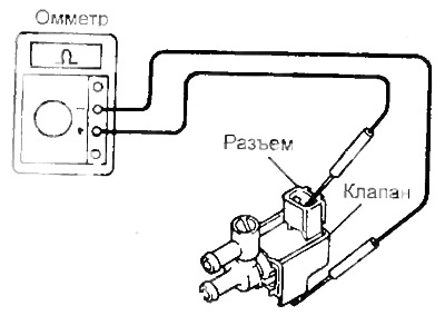
If the ohmmeter registers any resistance other than infinity. then replace the valve.
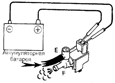
4. Check valve operation:
A) Make sure air is not leaking from the port "E" to port "F" through the valve.
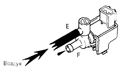
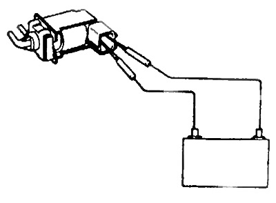
b) Apply voltage from the battery to the valve connector terminals and check that air is passing through the DC "E" to port "F". Otherwise, replace the valve.
5. Replace the valve.
Checking the EVAP Valve
1. Measure the resistance between the valve terminals.
- Resistance - 30-33 Ohm
2. Apply battery voltage and check valve operation
Voltage:
- Submitted - air passes
- Not supplied - air does not pass
Check valve check
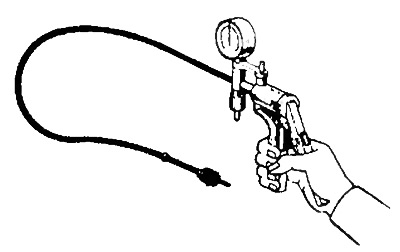
1. Create a vacuum of 500 mm in the blue part of the valve. rt. Art. and make sure the vacuum is being held.
2. Create a vacuum in the black side of the valve and make sure that the air passes without resistance.
Oxygen sensor
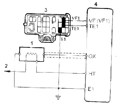
Scheme of switching on the oxygen sensor (3S-FE, 4S-FE).
1 - oxygen sensor,
2 - to the main relay of the fuel injection system,
3 - diagnostic connector,
4 - electronic control unit.
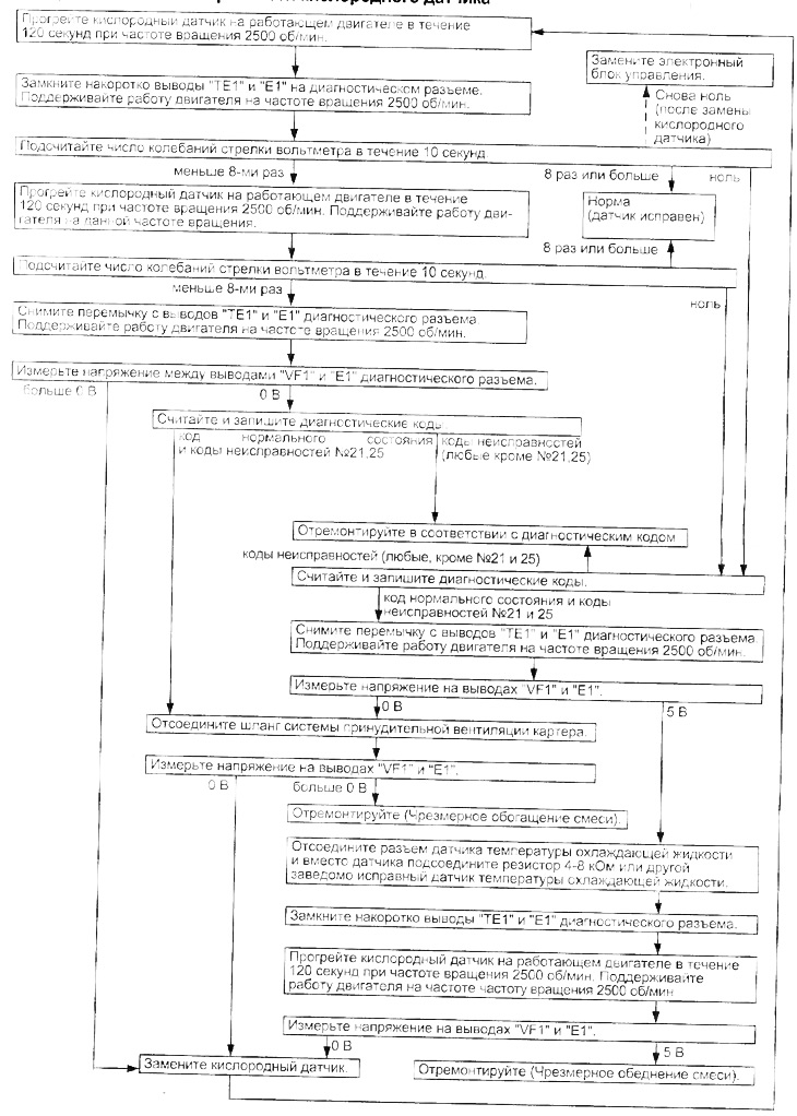
Oxygen sensor test
1. Warm up the engine to normal operating temperature.
2. Measure the oxygen sensor feedback voltage.
Connect the positive lead of the voltmeter to the "VF1" diagnostic connector, and the negative terminal to the output "E1".
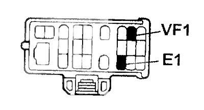
Then do a test (see below).
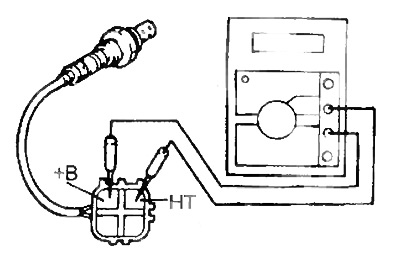
3. Check the resistance of the oxygen sensor heater.
Check resistance between terminals "+V" And "NT".
- Resistance (at 20°C) - 11 -16 Ohm
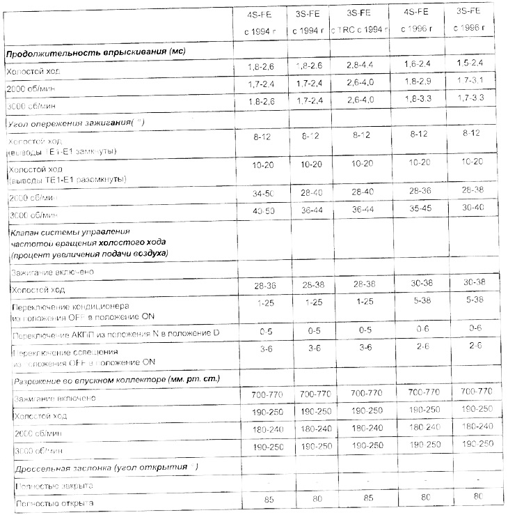
Checking the elements of the injection system
Table. Checking the elements of the injection system.
Algorithm for troubleshooting the oxygen sensor