
Fuel system
Fuel at constant differential pressure (284 kPa) is supplied by the fuel pump through the filter to the injectors, which inject fuel into the intake manifold pipes just before the intake valves. The amount of fuel supplied is determined by the duration of the control pulse, which is set in accordance with the signal from the electronic control unit.
The fuel pressure regulator maintains a constant difference between the fuel pressure before the working injector and the air pressure in the intake manifold. In this case, the amount of fuel supply is uniquely determined by the time of the open state of the injector. The regulation is carried out by bypassing part of the fuel into the tank through the valve and the fuel return line.
Air supply system
The air supply system supplies the required amount of air to the intake valves.
The amount of air entering the engine is determined by the throttle opening angle and the engine speed. The air flow passes through the air filter, the throttle body channel and enters the upper part of the intake manifold, from where it is distributed through separate pipes to the engine cylinders.
At low coolant temperatures, the idle speed control valve opens and some air enters the top of the intake manifold through the bypass in addition to the air passing through the throttle. Thus, as the engine warms up, even at a fully closed throttle, air enters the upper part of the intake manifold, which leads to an increase in engine speed (1st stage idle speed control).
Upper intake manifold reduces airflow pulsations (acts as a receiver or resonator), and also prevents the imposition of the work of some cylinders on others.
Electronic control system
The engines are equipped with the company's electronic control system "TOYOTA", which controls fuel injection, ignition timing, diagnostic system, etc. using an electronic control unit.
Through the electronic control unit, the fuel injection control system performs the following functions:
1. Fuel injection control. The electronic control unit receives signals from various sensors that register changes in the state of engine operation. In particular, the sensors register:
- absolute pressure in the intake manifold,
- intake air temperature,
- coolant temperature,
- engine crankshaft speed,
- throttle opening angle
- oxygen content in exhaust gases, etc.
These signals are processed in the electronic control unit, which produces a fuel injection duration output signal that provides the optimum excess air ratio for the current engine operating conditions.
2. Ignition timing control.
The memory of the electronic control unit contains the values of the optimal ignition timing for all possible engine operating modes. Using the signals of various sensors that control the operating conditions of the engine (crankshaft speed, coolant temperature, etc.), the electronic control unit generates impulses that control sparking at strictly defined points in time.
3. Idle speed control system.
The memory of the electronic control unit contains the data of the optimal idle speed that meets various conditions (e.g. coolant temperature, air conditioner on/off, etc.) Sensors send signals to an electronic control unit that controls the airflow through the bypass (bypassing the throttle) and regulates the idle speed according to the set value.
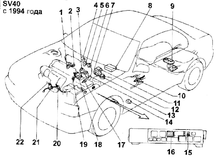
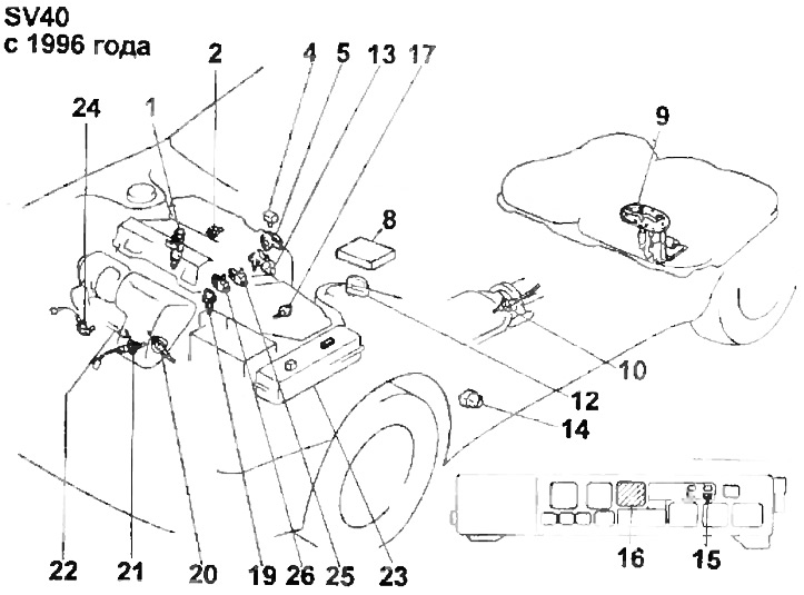
The location of the components of the electronic fuel injection control system.
1 - nozzle,
2 - knock sensor,
3 - additional throttle servo,
4 - absolute pressure sensor,
5 - throttle position sensor,
6 - additional throttle position sensor,
7 - electronic control unit of the traction control system (TRC),
8 - electronic control unit,
9 - fuel pump,
10 - oxygen sensor (3S-FE, front wheel drive),
11 - switch,
12 - diagnostic connector,
13 - idle speed control valve,
14 - circuit opening relay,
15 - injection system fuse,
16 - the main relay of the injection system,
17 - intake air temperature sensor,
18 - Distributor,
19 - coolant temperature sensor,
20 - oxygen sensor (4S-FE, 3S-FE, 4WD),
21 - oxygen sensor (3S-FE, front wheel drive),
22 - exhaust gas temperature sensor (4S-FE, 3S-FE, 4WD),
23 - fuse and relay box,
24 - crankshaft position sensor,
25 - ignition coil No. 2,
26 - ignition coil No. 2.
4. Diagnostics.
The electronic control unit warns of a malfunction or abnormal operation by means of a pointer "CHECK ENGINE", displayed on the instrument panel. The fault is identified in the form of a diagnostic code, which is stored by the electronic control unit. The diagnostic code can be deciphered by the number of flashes of the indicator light when the contacts are shorted "TAG" And "EG". Diagnostic codes are discussed below.
5. Function "Fail-Safe" ("Get home").
In case of failure of any sensor, emergency operation is provided (to get to the nearest service station). At the same time, the control lamp on the instrument panel lights up "CHECK ENGINE".