
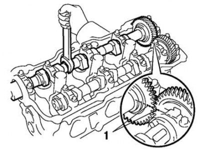
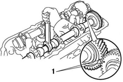
Pic. 2.249. Alignment marks on the drive and driven gears of the camshafts: 1 - labels
To remove the intake valve shaft of the rear cylinder head, align the alignment marks on the drive and driven gears of the camshafts, as shown in Figure 2.249.
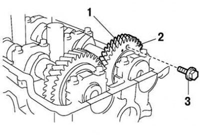
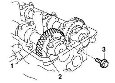
Pic. 2.250. Auxiliary gear mount: 1 - main gear; 2 - auxiliary gear; 3 - technological bolt
Attach the exhaust camshaft sub gear to the main gear with a service bolt (pic. 2.250).
Recommended process bolt:
- thread diameter - 6 mm;
- thread pitch - 1.0 mm;
- bolt length - 16–20 mm.
Before removing the intake camshaft, make sure that the auxiliary gear is securely fixed with a technological bolt.
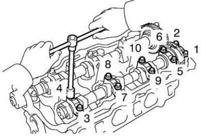
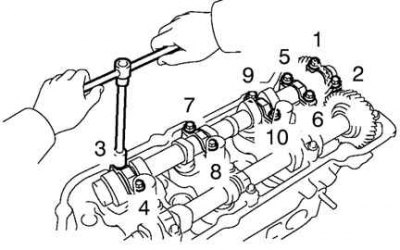
Pic. 2.251. The procedure for loosening the bolts securing the bearing caps of the intake valves of the rear cylinder head
Evenly weaken and remove ten bolts of fastening of covers of bearings in several passes, in the sequence specified in drawing 2.251.
Remove the five bearing caps and camshaft.
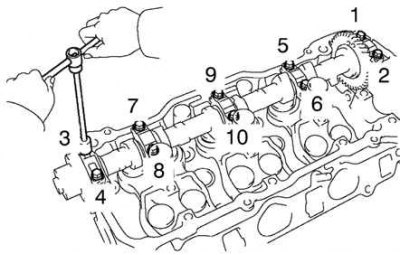
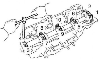
Pic. 2.252. The procedure for loosening the bolts securing the bearing caps of the exhaust valves of the rear cylinder head
For removal of a shaft of final valves of a back head of the block of cylinders evenly weaken and remove ten bolts of fastening of covers of bearings in several passes, in the sequence specified in drawing 2.252.
Remove the five bearing caps, oil seal and camshaft.
Pic. 2.253. Alignment marks on the drive and driven gears of the camshafts: 1 - labels
To remove the intake valve shaft of the front cylinder head, align the alignment marks on the drive and driven gears of the camshafts.
Pic. 2.254. Auxiliary gear mount: 1 - main gear; 2 - auxiliary gear; 3 - technological bolt
Attach the exhaust camshaft sub gear to the main gear with a service bolt (pic. 2.254).
Recommended process bolt:
- thread diameter - 6 mm;
- thread pitch - 1.0 mm;
- bolt length - 16–20 mm.
Before removing the intake camshaft, make sure that the auxiliary gear is securely fixed with a technological bolt.
Pic. 2.255. The procedure for loosening the bolts securing the bearing caps of the intake valves of the rear cylinder head
Evenly weaken and remove ten bolts of fastening of covers of bearings in several passes, in the sequence specified in drawing 2.255.
Remove the five bearing caps and camshaft.
Pic. 2.256. The procedure for loosening the bolts securing the bearing caps of the exhaust valves of the rear cylinder head
For removal of a shaft of final valves of a back head of the block of cylinders evenly weaken and remove ten bolts of fastening of covers of bearings in several passes, in the sequence specified in drawing 2.256.
Remove the five bearing caps, oil seal and camshaft.