
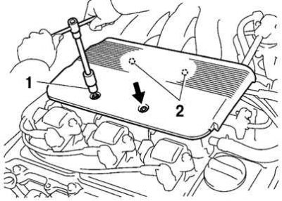
Pic. 2.242. Removing the engine protective cover: 1 - end key; 2 - clips
Using a 5mm socket wrench, unscrew the two nuts and remove the top protective cover (pic. 2.242).
Remove the upper intake manifold assembly. Disconnect the following wires and connectors:
- throttle position sensor connector;
- idle speed control valve connector;
- connector for the electro-pneumatic valve of the intake manifold geometry change system (ACIS);
- connector for the electropneumatic valve of the fuel pressure control system;
- diagnostic connector from the bracket on the auxiliary air valve.
Disconnect:
- brake booster vacuum hose from the ACIS auxiliary air supply valve;
- crankcase ventilation hose from the crankcase ventilation valve on the rear cylinder head;
- clamp and ground wire from ACIS auxiliary air valve;
- ground wire from the top of the intake manifold;
- vacuum hose clamp from the fuel pipe;
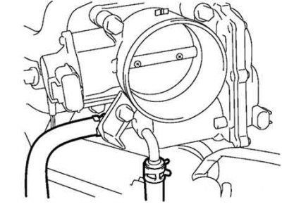
Pic. 2.243. Coolant bypass hoses
- two coolant bypass hoses from the throttle body (pic. 2.243);
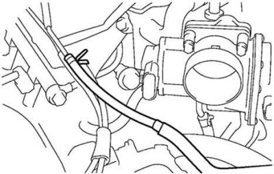
Pic. 2.244. Throttle Body Auxiliary Air Hose
- air supply hose from throttle body (pic. 2.244);
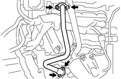
Pic. 2.245. Power Steering Air Hoses
- two power steering air hoses from the top of the intake manifold (pic. 2.245);
- two vacuum hoses from tubes on the head plate;
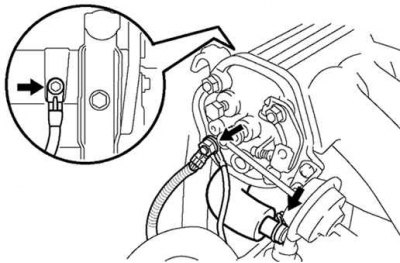
Pic. 2.246. Fuel Pressure Regulator Vacuum Hose
- vacuum hose from fuel pressure regulator (pic. 2.246).
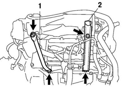
Pic. 2.247. Fasteners for engine bracket #1 and upper intake manifold strut: 1 – a rack of the top part of an inlet collector; 2 - bracket No. 1 of the engine
Remove the two bolts and remove the engine bracket #1. Loosen the two bolts and remove the upper intake manifold strut (pic. 2.247).
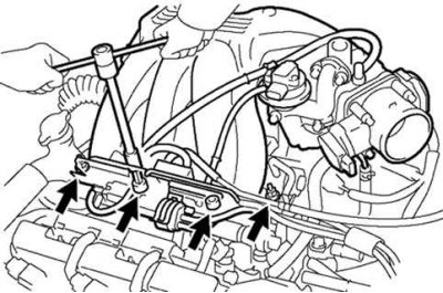
Pic. 2.221. Removing the upper part of the intake manifold
Using an 8mm socket wrench, remove the two bolts and two nuts and remove the upper intake manifold assembly and gasket (see fig. 2.221).
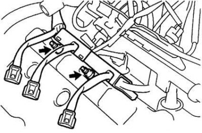
Pic. 2.222. Removing the wiring protection
Remove intake manifold assembly (see fig. 2.222).
Disconnect the six injector connectors.
Disconnect:
- inlet fuel hose from the fuel filter;
- fuel return hose from fuel return tube;
- heater hose from the intake manifold.
Remove nine bolts, two nuts, two washers, intake manifold, fuel manifold and injector assembly.
Remove the cooling system outlet pipe by unscrewing the two bolts, two nuts and disconnecting the coolant bypass hose, then remove the two gaskets.
Remove ignition coils.
Remove spark plugs.
Remove the timing belt.
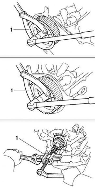
Pic. 2.248. Removing the camshaft pulleys and intermediate pulley: 1 - special tool
Remove the camshaft pulleys and intermediate pulley (pic. 2.248).
Remove the #3 timing belt cover by unscrewing the 6 bolts and disconnecting the three wiring clips.
Remove the engine wiring protection from the flywheel. Unscrew the two nuts and disconnect the wiring protection from the rear cylinder head and the cooling system inlet pipe. At the rear of the engine, remove the five nuts and disconnect the two wire guards from the rear cylinder head. At the front of the engine, unscrew the two nuts and disconnect the wiring protection from the front cylinder head.
Unscrew the bolt and disconnect the coolant supply pipe from the inlet pipe of the cooling system, remove the O-ring from the pipe.
Remove the rear heat shield by removing the three bolts. Remove the six nuts and remove the rear exhaust manifold with gasket.
Remove the front heat shield by removing the three bolts. Remove the six nuts and remove the front exhaust manifold with gasket.
Remove the camshaft position sensor.
Remove the cylinder head covers by removing the eight mounting bolts.