
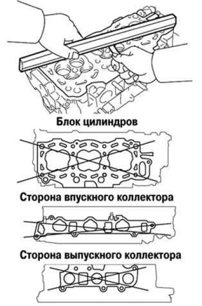
Pic. 2.263. Checking the cylinder head
With a precision ruler and a flat feeler gauge, as shown in Figure 2.263, check the warping of the working surfaces of the cylinder head mating with the surface of the cylinder block and with the surfaces of the intake and exhaust manifolds.
Maximum allowable surface distortion:
- cylinder block - 0.05 mm;
- collectors - 0.08 mm.
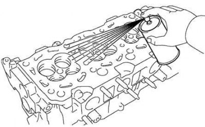
Pic. 2.264. The use of dye when checking the cylinder block
If the amount of warpage exceeds the maximum allowable, replace the cylinder head or grind it. Using a penetrating dye, check for cracks in the combustion chambers, inlet and outlet ports, and at the gas interface (pic. 2.264).
If there are cracks, replace the cylinder head or weld it (followed by polishing). Welding of cracks in the cylinder head must be carried out in specialized workshops. Clean the valves, to do this, remove the carbon deposits from the valve plate with a scraper, then finally clean the valve with a brush.
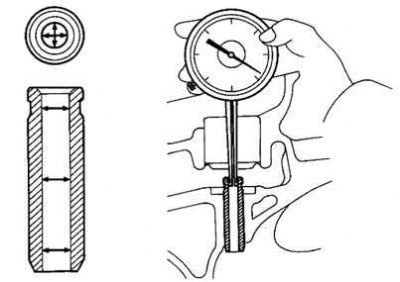
Pic. 2.265. Measuring the internal diameter of valve guides with a caliper
Check the diameters of the valve stems and the inner diameters of the valve guides, to do this, measure the inner diameter of the valve guides with an inside gauge (pic. 2.265).
Sleeve inner diameter: 1MZ-FE - 5.510-5.530 mm.
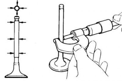
Pic. 2.266. Measuring the valve stem diameter with a micrometer
Also measure the diameter of the valve stem with a micrometer (pic. 2.266).
Valve stem diameter:
- intake valve - 5.470–5.485 mm;
- exhaust valve - 5.465–5.480 mm.
Find the gap between the valve stem and guide by measuring the difference between the valve stem diameter and the inner diameter of the valve guide.
Standard oil clearance:
- intake valve - 0.025–0.060 mm;
- exhaust valve - 0.030–0.065 mm.
Max oil clearance:
- intake valve - 0.08 mm;
- outlet - 0.10 mm.
If the clearance is greater than the maximum, replace the valve and guide bushing.