Anchor check
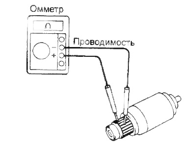
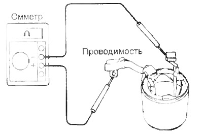
1. Check that the armature winding is not loose.
Using an ohmmeter, check for continuity between the collector fins. If there is no continuity, replace the armature.
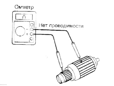
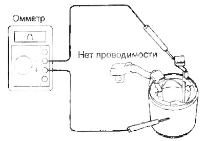
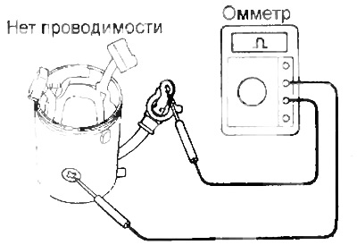
2. Check that the armature winding is not shorted to "earth".
Using an ohmmeter, check for continuity between the collector and the armature core.
If continuity is present, replace armature.
Manifold check
1. Check the working surface of the collector for dirt and carbon deposits.
If the surface is dirty or there are traces of soot, treat with sandpaper (№ 400) or turn on a lathe.
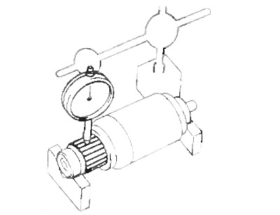
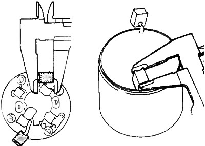
2. Check manifold runout
A) Install the manifold on the test stand.
b) Using an indicator, measure the runout of the collector.
- Maximum runout - 0.05 mm
If the runout is more than the maximum allowable, machine the manifold on a lathe.
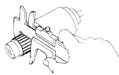
3. Measure the diameter of the manifold
Use a caliper to measure the diameter of the manifold*.
3S-FE, 4S-FE:
- Nominal diameter - 30 mm
- Minimum diameter - 29 mm
ZS-T:
Nominal diameter:
- starter 1.4 kW - 30.0 mm
- starter 2.0 and 2.2 kW - 35.0 mm
Minimum Diameter:
- starter 1.4 kW - 29.0 mm
- starter 2.0 and 2.2 kW - 34.0 mm
If the diameter is less than the minimum allowable, replace the anchor.
Check the depth of the groove between the collector lamellas.
Check the absence of foreign particles in the grooves between the lamellas.
Nominal diameter:
3S-FE, 4S-FE - 0.6 mm
ZS-T:
- starter 1.4 kW - 0.5-0.8 mm
- starter 2.0 and 2.2 kW - 0.7 - 0.9 mm
Minimum diameter - 0.2 mm
If the value is less than the minimum allowable, process the grooves of the hacksaw.

Stator check
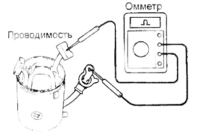
1. Check for an open field winding.
Use an ohmmeter to check for continuity between the brush terminal and the field winding terminal.
If there is no continuity, replace the stator.
Starter 1.4 kW
Starter 2.2 kW
2. Check the absence of a short circuit in the field winding on "earth".
Using an ohmmeter, check for continuity between the field winding terminal and the stator.
If there is continuity, replace the stator.
Starter 1.4 kW
Starter 2.2 kW
Checking the brushes
1. Using a vernier caliper, measure the brush length.
Nominal length:
- 3S-FE, 4S-FE - 13.5 mm
ZS-T:
- starter 1.4 kW - 15.5 mm
- starter 2.0 and 2.2 kW - 15.0 mm
Minimum length:
- 3S-FE, 4S-FE - 8.5mm
ZS-T:
- starter 1.4 kW - 10.0 mm
- starter 2.2 kW - 9.5 mm
If the length is less than the minimum, replace the brush holder and stator.
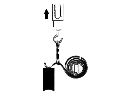
Checking brush springs
Use the steelyard to measure the tension of the brush springs at the moment of their separation from the brush.
Rated tension:
- 3S-FE, 4S-FE - 18-24 N
ZS-T:
- starter 1.4 kW - 15-18 N
- starter 2.0 and 2.2 kW - 26-32 N
If the spring tension is not within the specified range, replace the spring.
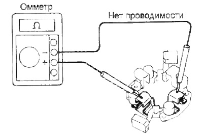
Checking the brush holder
Check brush holder insulation. Using an ohmmeter, check for continuity between the positive and negative brush holders.
If there is conductivity, repair or replace the brush holder.
Checking the freewheel and gears
1. Inspect the running surfaces of the drive and idler gear teeth and freewheel gear for excessive wear or chipping.
Replace gears if worn or damaged.
If there are scores or chips on the surfaces of the freewheel gear teeth, check the running surfaces of the flywheel ring gear teeth.
2. Check freewheel.
Check that the drive gear rotates clockwise freely and counterclockwise does not rotate.
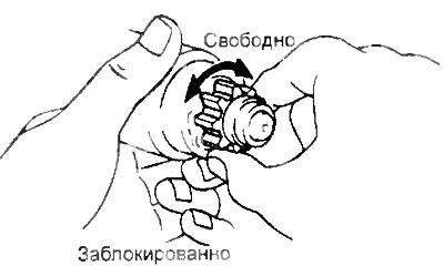
If conditions are not met, replace freewheel.
Bearing check
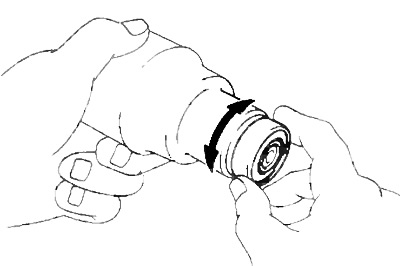
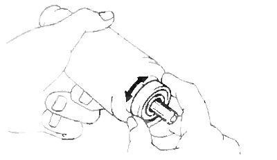
1. Check the front bearing Rotate the bearing by hand while applying an axial force towards the center of the armature.
If there is excessive resistance or seizing, replace the bearing.
2. If necessary, replace the front bearing.
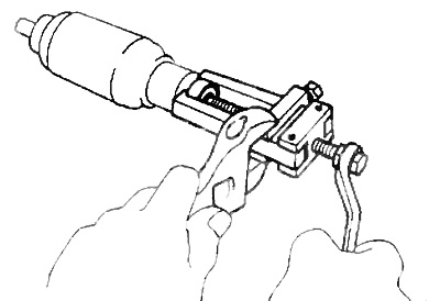
A) Remove the bearing using a puller.
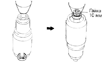
b) (Starter 1.4 and 2.0 kW) Using a press, press in the new bearing.
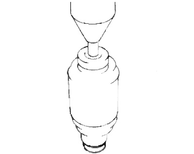
V) (Starter 2.2 kW) Using a 10 mm nut and a press, press in the new bearing.
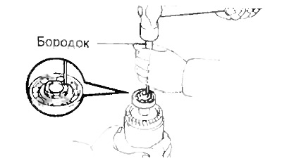
G) (Starter 2.2 kW) Using a beard, open the armature shaft.
3. Check the rear bearing.
Rotate the bearing by hand while applying an axial force towards the center of the armature.
If there is excessive resistance or seizing, replace the bearing.
4. If necessary, replace the rear bearing
A) Remove the bearing using a puller
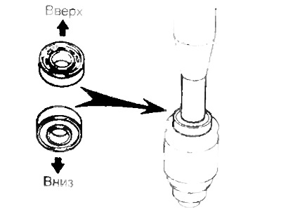
b) Using a drift and a press, press in the new bearing.
Note: Make sure you install the bearing in the correct direction.
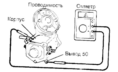
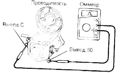
Checking the traction relay
1. Check for an open circuit in the pull-in winding.
Using an ohmmeter, check for continuity between the terminals "50" And "WITH".
If there is no continuity, replace the traction relay.
2. Check for an open in the holding winding.
Using an ohmmeter, check that there is continuity between the terminal "50" and relay housing.
If there is no continuity, replace the traction relay.