
Hazard light switch
Hazard light switch and diagram for testing it
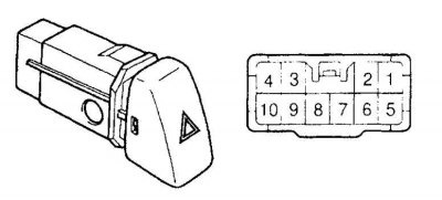
| Switch position | Tested Conclusions | The presence of a chain |
| OFF (switched off) | 7 – 10 | There is a chain |
| ON (included) | 5 – 6 – 9 – 7 – 8 | There is a chain |
| lighting circuit | 2 – 3 | There is a chain |
The switch is mounted in the central part of the instrument panel.
Examination
Check for continuity between the indicated terminals. Replace the switch if any of the tests fail.
Replacement
1. Remove facing in the central part of the panel of devices.
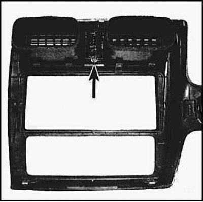
2. Move the switch up and disconnect the connector, press the latch (arrow) and take out the switch.
Mirror Power Switch
Mirror Power Switch (Camry, Solara)
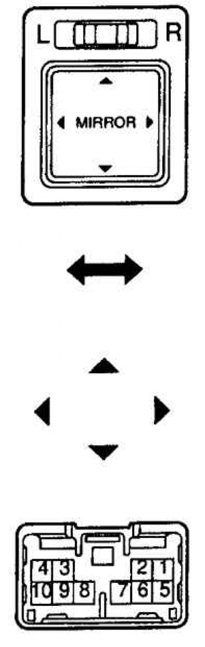
| Switch position | Tested Conclusions | The presence of a chain |
| Off | – | no chain |
| Up | 1 – 9, 6 – 10 | There is a chain |
| Down | 1 – 10, 6 – 9 | There is a chain |
| Left | 5 – 9, 6 – 10 | There is a chain |
| right | 5 – 10, 6 – 9 | There is a chain |
| Switch position | Tested Conclusions | The presence of a chain |
| Off | – | no chain |
| Up | 6 – 10, 7– 9 | There is a chain |
| Down | 6 – 9, 7– 10 | There is a chain |
| Left | 6 – 10, 8– 9 | There is a chain |
| right | 6 – 9, 8– 10 | There is a chain |
Mirror Power Switch (Avalon)
Switch position | Tested Conclusions | The presence of a chain |
Off | – | no chain |
Up | 1 – 9, 6 – 10 | There is a chain |
Down | 1 – 10, 6 – 9 | There is a chain |
Left | 5 – 9, 6 – 10 | There is a chain |
right | 5 – 10, 6 – 9 | There is a chain |
Switch position | Tested Conclusions | The presence of a chain |
Off | – | no chain |
Up | 6 – 10, 7– 9 | There is a chain |
Down | 6 – 9, 7– 10 | There is a chain |
Left | 6 – 10, 8– 9 | There is a chain |
right | 6 – 9, 8– 10 | There is a chain |
The switch is mounted on the instrument panel on the left side - under the vent nozzle on Camry and Avalon models, or to the right of the nozzle on Solara models.
Examination
1. Check for continuity between the indicated terminals. Replace the switch if at least one of the tests fails.
Replacement
1. Carefully pry up and remove the switch.
2. Disconnect the connector and remove the switch.
3. Install the switch in reverse order.
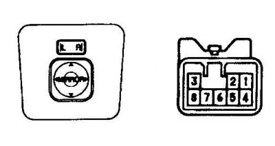
Traction control switch
The traction control switch works in conjunction with the ABS system to improve traction in certain road conditions. The switch is mounted on the panel to the left of the steering wheel.
Examination
1. Check for continuity between the switch terminals by pulling it out. When pressed, the contacts should close, and when released, they should open. Otherwise, replace the switch.
Replacement
1. Carefully pry up and remove the switch.
2. Disconnect the connector and remove the switch.
3. Install the switch in reverse order.
Light switch on the instrument panel
Checking the light switch on the instrument panel
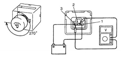
When the handle is rotated, the voltage between pins 2 and 3 should change.
On the vehicles in question, either a rotary light switch is used, which is mounted in the upper left part of the instrument panel, or a switch with a remote handle located under the left air vent on the instrument panel. Switches of both types are combined with a rheostat, which is designed to control lighting.
Examination
1. On the removed switch, check the rheostat, for which make the connections according to the diagram (see fig. Checking the light switch on the instrument panel). When the handle is rotated, the voltage between pins 2 and 3 should change. Otherwise, replace the switch.
Replacement
On vehicles with a lighting rheostat under the left nozzle, pry up and remove the switch. To replace the rotary switch, the instrument panel must be removed.